Creating Control Tags for Motor Current etc....

Harmonizer88

Member
Join Date
Dec 2015
Location
Richland
Posts
7
Hello friends! I am new here!

First question is:

I am trying to make a display to control an agitator using a Pflex 525 and I do not see a control tag, input/output tag in RSLogix 5000 that I can do this with.

There was a previous 525 motor where this was accomplished. The K_9000 motor has this control tag but how do I know it is connected to the 525 actual output current output?

These are the control tags for K_9000 which is a 525 VFD
View attachment 41224

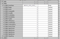
Here are the control tags for my 525.
View attachment 41225

How do I create a control tag that shows me the M_3800 output current? How did the guy before me do it for the K_9000?
1.PNG 3.PNG
 
Welcome to the forum!

First the control tags on K_9000 are not derived from the drive itself, looks like the programmer created those tags. You would have to cross reference those to see where it's getting the data.

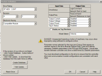
You can pull additional data from a drive using data links. Open up the drive's module properties in the hardware tree, then click "Change..." in the module definition area. You can then choose additional data from the drop downs. See attached picture. You could also get it from MSG instructions. Read the user manual of the comm adapter you are using.

Capture.PNG
 
Yes- Like Paully said, the last 5 K9000 tags in your picture were created manually and are either pulled from the drive and scaled/computed, or just aliased directly to the PF525 data registers.
 
Fellas,

I did what Paully5 suggested and pulled the data from the drive. So far so good. THANK YOU

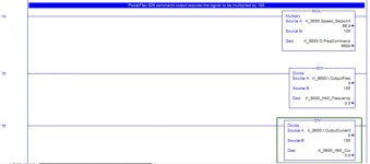
Furthermore, I cross referenced the K_9000 tags and found them inside of a routine with the attached note:

1.jpg

Any clue what he's talking about?

I would also like to say that I am an INTERN and I am totally new to PLC. Learning as fast as I can and I greatly appreciate the help. When I graduate next year I'll be taking over this position here at my company, and I am working under the guy who wrote all of this code I am questions ya'll about. Thanks for your time.
 
Yes-He's scaling the actual feedback from the drive and writing to an HMI tag that will be displayed on a panelview or scada/hmi.

The drive feedsback 6000 for 60.00Hz, And 2450 for 24.50 amps. He just divides by a 100 so it is displayed correctly.

The MUL, he is taking the HMI setpoint of 66, multiplying it by a 100, and sending to the drive control word as 6600. The drive interprets this as 66Hz.
 

Similar Topics

Hello friends! I am new here! First question is: I am trying to make a display to control an agitator using a Pflex 525 and I do not see a...
Replies
2
Views
1,618
Hi everyone, I am trying to create a medium sized Citect SCADA project utilising a Control Logix PLC. I want to adopt good practice from the...
Replies
0
Views
2,351
Does anyone know if Control Plus software used to create SAMA drawings still exist? IF so, please post a reply where I can find/buy the software?
Replies
0
Views
1,329
Can anyone recommend a book, publication or website for learning to create control panel wiring diagrams? I know there are standard electrical...
Replies
1
Views
1,602
Hi all, I am wondering if it is possible to create a keypad that can be used by an operator to give each data log a name and equipment number...
Replies
3
Views
3,722
Back
Top Bottom