double acting cylinder

PERSPOLIS

Member
Join Date
Jun 2002
Location
ontario
Posts
295
HI EVERYONE
I have a double acting cylinder as a diverter.I want to write a program to do the following steps.
Parts are droped in left chute and counted say 50 once 50 parts are done then counter reset to zero at the same time the cylinder is activated and moves to other direction.
Again 50 parts are counted and cylinder is moved to other side and process repeat itself. I need some advice how to go about it, For this project I do not use proxy switch only one cylinder with a solenoid valve having one coil on each side.In addition I also use a external counter and reset pulse given to plc.
Thanks a lot.
 
TRY giving a little more info such as does the external counter only give a digital input to the plc when it reaches a count of 50? and what type of plc. do you have any existing programs or routines associated with counter in the plc and have started writing any code for this app.?
 
One external counter or two? If one external counter use its output to one input to a basic flip-flop, two outputs.
If two external counters,use their outputs on two inputs and use standard three-wire start-stop logic to control two outputs, one in the start mode, the other in the stop mode. Use a separate output derived from either of the outputs to trigger the reset on the counter.
Maybe this is not clear but it's a start.
 
Last edited:
Generate a 1 shot from each counter input pulse.
Use this 1 shot to increment a register.
Use the least significant bit of this register to control the flap direction.
If the bit is high turn on one output
if the bit is low turn on the other output.
Use a comparator to reset the register if the value gets too great.
The register can also be used to count the batches of 50
 
Thank you all for your input and sorry for the lack of info.
I use only one sensor to generate count pulses which connected directly to external counter.I will utilize AB RS LOGIX 500 program.
In regards to programming nothing important done yet.Thanks
 
Perspolis,
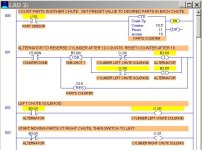
It is probably easier to do it with an internal PLC counter.

1 BEGIN IN RIGHT CHUTE-  10 COUNT.jpg 2 ON COUNT 11 LEFT CYLINDER GOES ON.jpg 3 AFTER 10 MORE RIGHT GOES ON AGAIN.jpg
 
Last edited:
Yes, using an external counter would only be advantageous if it already exists as the sole HMI for operators.

If this is the case, then you are monitoring the counter done signal with an input? What is the duration (in seconds) of this signal? Do you have to send a reset signal to the counter or is it programmed to self reset?

Your logic will simply switch the position of the outputs and time them.

I would start with a time delay, use this to offset for the physical delta T of the system. If the photo eye is well ahead of the diverter, and the counter signal is almost instantaneous, you may need to wait up to several seconds.

Use a 0.01 second timebase. You can always zero it, but have it there for field tuning.

You will also want to know if this valve is a three position or a two position valve. If it's a dangerous pinch point, you will prefer that it is 3 position open center or safety dump valve controlled. This may affect how you want to write the control code. With no position feedback, and low pressures, it can be safe as a simple adjustable on delay lane switcher. I would also have timers to restrict short cycling the valves. the lane switch sequence would be non-interruptible so as to be gentle on the solenoid coils. Match these timers to the real world response time of the actuators after you get the flow controls (pneumaatic) adjusted suitably.
 
Last edited:
Thank you all for your help.
I need to correct that I only use one photocell to count the parts and one external counter and reset signal comes from the external counter to be honest with you I have not touched plc for about a year and as said (if you do not use you loose it) now I am in the same situation so I am getting back to basic but I have some question:
For Liam my assumption is that you are referring to BSL or BSR if is so then I need two pulse one for enable bit and for data insertion to instruction so I am a bit lost here.
Lancie1 I am reviewing what have suggested it looks cool. OkiePC all to be considered.
Thank you.
 
HELLO EVERYONE
what is preffered regarding counting parts using proxy switch :
1- direct signal count from proxy switch to plc input.
2- use a relay from proxy signal output to plc input.
3- is there any advantage to use osr bit in a rung to the counter instruction. Thanks
 
1- Use a direct signal count from proxy switch to plc input, by all means. There is no need for anything in between, this will save time and money.

3- Is there any advantage to use osr bit in a rung to the counter instruction? With your RSLogix program, there is no need to have a OSR in front of a counter UNLESS your input pulse will stay on longer than any Counter Reset bit. In other words, for fast applications, your counter might reach done, get reset, but the prox switch is still seeing the last part counted (so it would get counted again after the counter gets reset). Normally for counting parts at a moderate speed, you would not need a OSR unless you are talking about very fast rates.
 
Last edited:
1-Direct is preferred. It can be protected from external adjustment and simplify things electrically for reliability. Direct can be prohibited by duty cycles that exceed the input frequency rating of the PLC point. This is what I have seen as the main reason for using external high speed counters for usually about the same cost, but simpler to implement than add on high speed cards in a PLC for many people. But, that counter value can be much much more useful if the PLC is fast enough to be in charge, tying that little spider eye into the machine controller gives you all sorts of extra power and diagnostics, and I have forgotten the specs of this original author's application, so forgive me if frequency was already covered.

2-The relay would only be used if required to switch voltages, isolate noise, or provide electrical isolation to meet some specific requirement. I would be more likely to relay isolate an output, and replace any local sensors with ones that match my PLC input. Relays will add input latency. Input latency is not your friend.

3-You should decide what you want the counter to do in certain situations, but the OSR is usually not required. It might be handy to have there if you have other instructions in parallel with the CTU that also shoud fire once, and depending on the preceding logic, can affect how your counter reacts on power up with the input sensor true. This is normally not an issue, but some machines do get power cycled a lot and must consider these things in great detail.
 
Last edited:
1-Direct is preferred. It can be protected from external adjustment and simplify things electrically for reliability. Direct can be prohibited by duty cycles that exceed the input frequency rating of the PLC point. This is what I have seen as the main reason for using external high speed counters for usually about the same cost, but simpler to implement than add on high speed cards in a PLC for many people.

Just to elaborate a little on what OkiePC says, it's important to considder the "apparent" frequency of the input. If the sensor detects 1 object per second then that would imply a frequency of 1Hz but if the signal is only true for 100ms then the apparent frequency would be 10Hz. To be able to guarantee detecting the pulse, the input card must update at double the apparant frequency or faster and the cycle time of your PLC program will also need to be faster still to avoid missing pulses.

Nick
 
HI LANCIE 1
I put your program into test and c5:0 before reaching to preset value goes to acc value of 1 (after counter being reset) but everything else works fine.
I did insert OSR in the first rung (counter block)and result just fantastic.
Thanks.
 
I did insert OSR in the first rung (counter block)and result just fantastic. Thanks.
Did you decide to go with the internal PLC counter, instead of the external counter?
 

Similar Topics

Hi, guys. At first sorry for my english, im not english speaker. Im trying learn ladder and i cant figure out this sequence; i have 2 push...
Replies
5
Views
2,320
I have double acting valve. this need to be opened and closed . now Valve remain open as long as power is connected to slenoid on power loss...
Replies
4
Views
1,565
Dear, my question is what is the difference between single acting and double acting float switch, is it only the counterweight? or it should have...
Replies
1
Views
2,959
I'm going to connect a double acting solenoid valve to a plc ... In one of the forums I read that the double acting SV does not have an initial...
Replies
7
Views
4,013
Hello, I have a question about getting individual bit information from a double word using Siemens S7. We use Siemens OP panels and the alarm...
Replies
4
Views
13,221
Back
Top Bottom