Fatek modbus data reading

Join Date
Jul 2021
Location
Bulgaria
Posts
51
Hi,

I have been struggling for a week with FATEK FBs-24-MAR-AC PLC.

My goal is to read voltage and current from a powermeter Elnet Pico 5.

The data should be read as floating point i.e. 230.5 Volts or 4.9 Amperes, one digits precision after the decimal point.

I managed to read data as integer so far, the digits after the decimal point are not visible.

This is the powermeter communication manual: Communication Manual Elnet Pico 5

MODBUS TABLE ADDRESS READING

According to the manual I have to read MODBUS Registers 1 and 2 to get the Voltage of Line 1 as a floating point number.

This is the MODBUS instruction to initiate communication.

MODBUS Initiate Instruction

Then I get some integers in the register D1200 and D1201 (16 bit registers).

FATEK uses IEEE 754 standard for floating point numbers representation.

I tried following some guides for converting this raw number to float but with no success.

It would be great if you can give some hint about how to achieve the goal.

Best Regards
 
Welcome to the forum.


There are two choices:

  • you or I can do a lot of reading e.g.
    • here
    • and in the FATEK manual
OR

  • you can

  1. Put the value -1.0 into a 32-bit REAL tag, R, in the PLC,
    1. and post, in this thread the value of bit R.31, R.8, and R.0,
      1. e.g. use R.31 or whatever the syntax is to get a bit of a REAL tag.
  2. Post, in this thread, the two 16-bit integer values, I and J, you are getting from the Modbus read,
  3. Post what you think the corresponding floating point value result should be for the 16-bit integers I and J from the previous step.
  4. If you can post multiple (I,J,REAL-value) triplets for steps 2 and 3, that would be best.
  5. It would also help greatly to post the 16-bit integers values for registers 565, 566, 567, and 568 (564 and 569 also, just to be sure)
P.S. Registers 565 and 566 should be either [17142 and -13107], or [-12852 and -2494], or close.


P.P.S. if you have a voltage reading of 230.5, are you seeing 16-bit integers like [128 and 26179], or [17254 and -32768], or numbers close to that?
 
Last edited:
Welcome to the forum.


There are two choices:

  • you or I can do a lot of reading e.g.
    • here
    • and in the FATEK manual
OR

  • you can

  1. Put the value -1.0 into a 32-bit REAL tag, R, in the PLC,
    1. and post, in this thread the value of bit R.31, R.8, and R.0,
      1. e.g. use R.31 or whatever the syntax is to get a bit of a REAL tag.
  2. Post, in this thread, the two 16-bit integer values, I and J, you are getting from the Modbus read,
  3. Post what you think the corresponding floating point value result should be for the 16-bit integers I and J from the previous step.
  4. If you can post multiple (I,J,REAL-value) triplets for steps 2 and 3, that would be best.
  5. It would also help greatly to post the 16-bit integers values for registers 565, 566, 567, and 568 (564 and 569 also, just to be sure)
P.S. Registers 565 and 566 should be either [17142 and -13107], or [-12852 and -2494], or close.


P.P.S. if you have a voltage reading of 230.5, are you seeing 16-bit integers like [128 and 26179], or [17254 and -32768], or numbers close to that?
Hi,

Thank you for your fast response. I spent a lot of time on the Internet researching the IEEE 754 representation and wondering how to achieve this in the PLC environment.

Now I will give you some feedback.

I entered the value -1.0 in a 32 bit register and here is how to bits look like, DR1111 means that it is a double register R1111 and R1112, each register is 16 bits:
view

-1.0 in bits

These are the MODBUS addresses according to the manual of the power meter:
view

MODBUS ADDRESSES FROM MANUAL

Settings for the voltage reading using Function 03 and Function 04:
view

view

Voltage Settings Function 03
Voltage Settings Function 04

And this is how the register look like with respect to the MODBUS functions:
Voltage Values

view

It can be seen here, that with Function 04, I can see the actual voltage 244 Volts without the digits after the decimal point. But when requesting the voltage value via the Function 03, both of the integers do not change at all. They stay as they are in the picture. When I convert them to a floating point representation, it is not even close to 244 Volts.

Here are the register from R564 to R569, I do not know why you asked for them, since I do not think I use them for the MODBUS communication.
view

Registers R564 to R569

Now it gets a bit tricky with the current measurements. On the screen of the power meter I can see the current for Line 1 as, for example, 4.626 Amperes.

In the PLC register when using Function 04 I get 4 Amperes, which is fine, no digits after the decimal point. But when I try to ask for the current via Function 03. I get two integers in D1200 and D1201 (Data Registers). D1200 = 17248 and it does not change a lot, D1201 changes almost all the time. If I show D1201 as Decimal representation I get negative values as well. If I show D1201 as Unsigned Decimal representation I get positive values only up to 65535 and I think it overflows as well.

I tried plugging these values into a floating point convert and I get pretty close results.

Let's say the current on the power meter is 4.626 Amperes, the converter (it is an Excell Spreadsheet) shows 2.313E+02. This values is actually the right one if I divide by 100 and multiply by 2.

I will be able to post some values for current perhaps tomorrow.

Best Regards
 
Last edited:
Those results do not make sense.

1) The comm. manual on page 4 suggests the offset is 30000 (five decimal digits), but the example is using 400001 and 300001 (six decimal digits).

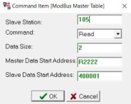
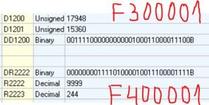
2) The DR2222/R2222/R2223 data use address 400001 (from setup JPEG; see below), which should be returning the 32-bit IEEE 754 FLOAT bits, but the INTEGER 244 (decimal) bits are in the high 16 bits i.e. in R2223.

2.1) The 9999 decimal value is suspicious; it could be coincidence, but if the Pico returns the voltage as a single 16-bit integer from one the two 16-bit registers 1-2 (page 7 in comm. manual), then it may also return the nonsense value 9999 in the other 16-bit register.

3) The 17948 decimal value in D1200, IF it is the high 16 bits of a 32-bit IEEE 754 floating point REAL value, suggests a floating point value between 224.0 and 224.9999..., which is in the ballpark of 244; perhaps it is the next pair of registers?

There does not appear to be enough published information about the details of the Fatek and Pico internal data storage conventions (byte order, word order, etc.), but it can be inferred if there are enough data. That being the case, I suggest OP gets the fours sets of 20 registers at these Modbus slave addresses:


  • 30000-30019
  • 40000-40019
  • 300000-300019
  • 400000-400019
And also report the known floating point values, read from the Pico I assume, of the first 18 Modbus Registers on page 8 of the comm. manual (Voltages; Voltages between lines; currents).

Notes

Setup JPEG:
MODBUS VOLTAGE READ SETUP.JPG
300001 and 400001 registers' results:
MODBUS VOLTAGE REGISTERS.JPG
 
Many vendors doing Modbus offer an integer value with a multiplier, for instance int * 0.01. So the integer 482 would be interpreted 4.82, but Fatek is on their own path and truncate anything to the right of the decimal point.

There's about an 80% chance that the PLC development software has a means of converting multiple-byte data words to a floating point value.

There are four standard word/byte orders for IEEE FP's. Most vendors off two of the four floating point formats.

searching for 'real' or 'floating point' might bring up that topic. It's not likely to be found in the hardware manual.

Another suggestion is that HMI's can frequently be a Modbus master and your HMI developement software might offer 'interpret as floating point' as a standard feature.
 
Byte-swapping and re-arranging into a 32-bit float is the best path, but we need to know how the 16-bit integer values from the Modbus registers reads map into the floats. I am still not convinced we know that yet.

Even if byte-swapping et al. are not available, the floating-point value can be arrived at mathematically with some bit manipulation from the value pair of 16-bit integers; it's messy but otherwise straightforward.
 
Last edited:
[FONT=&quot]@drbitboy
@danw

Thank you for your responses.

Now, after a lot of efforts, everything works flawlessly.

Apparently the Elnet PIC 5 MODBUS register are off by 2. I tried what you suggested - to read the first 20 registers. Apparently the 1st and 2nd register just shows the exact same numbers (17948 and 15360) all the time (I do not know why).

I move the data of the voltage register DD1202 (D1202 and D1203 registers) to DD2200 (D2200 and D2201 registers) and the data of the current register DD1214 (D1214 and D1215 registers) to D2214 (D2214 and D1215 registers) in order to manipulate the data after it has been received.

But the next two registers contain the floating number of the voltage for L1. The problem was that the High Order Word was swapped with the Low Order Word, therefore the float number was completely wrong. I swapped the Words and when I display the DD2200 registers as a float I get the exact same voltage that is on the display of the power meter.

[/FONT][FONT=&quot] On the picture below are the first 20 registers that are read with Function 30000x (300001-300020):[/FONT]
[FONT=&quot] Registers 300001-300020
[/FONT]
[FONT=&quot]On the picture below are the first 20 registers read with Function 40000x (400001-400020):[/FONT]
[FONT=&quot]Registers 400001-400020[/FONT]

[FONT=&quot]@drbitboy suggested to read registers 30000-30019 and 40000-40019, it does not allow me to enter these registers numbers. It always adds the extra 0 in order to get a 6 digit register number. One more thing is that it does not allow me to start reading from 3000000, always have to start from 300001. The same applies to the Function 04 registers.[/FONT]

[FONT=&quot]And finally, you can see the floating values for the voltage and current on the picture below:[/FONT]
[FONT=&quot] Voltage and Current Float Values
[/FONT]
[FONT=&quot]Thank you for your time and help!

Best Regards[/FONT]
 
I'm glad you got it to work.

For anyone who finds this thread in the future when chasing down a similar problem, here is one easy way to investigate the bits, bytes, integers and floats in Python; this example uses WSL (Windows System for Linux):
Code:
 $ python
 Python 3.8.8 (default, Apr 13 2021, 19:58:26)
...
>>> import struct[COLOR=Blue][B]

   First pass using native byte order (LSB-first):[/B][/COLOR]

>>> struct.unpack('f',struct.pack('HH',51483,17241))
 (217.7855682373047,)[COLOR=blue][B]  => a reasonable voltage value[/B][/COLOR]

>>> struct.unpack('f',struct.pack('HH',39182,16543))

 (4.987433433532715,)   [COLOR=Blue][B]=> a reasonable current value[/B][/COLOR]

[B][COLOR=Blue]   Second pass, MSB-first, but same order of 16-bit integers:[/COLOR][/B]

>>> struct.unpack('>f',struct.pack('>HH',39182,16543))
(-7.354278062363192e-24,)[COLOR=Blue]  [B]=> an unreasonable current value[/B][/COLOR]

[COLOR=blue][B]   Third pass, MSB-first, reverse order of 16-bit integers:[/B][/COLOR]

>>> struct.unpack('>f',struct.pack('>HH',16543,39182))
(4.987433433532715,)   [COLOR=Blue][B]=> a reasonable current value[/B][/COLOR]

>>> struct.unpack('>f',struct.pack('>HH',17241,51483))
(217.7855682373047,)   [COLOR=Blue][B]=> a reasonable current value[/B][/COLOR]
 >>>

Details


The function call [struct.pack('HH',51483,17241)] converts two the Python integers 51843 and 17241 into two 16-bit unsigned integers (the two H's in the string 'HH') using the CPU's native byte order, and concatenates all the the bits into a array of bytes a.k.a. byte string:
Code:
>>> struct.pack('H',[B][COLOR=Blue]51483[/COLOR][/B],[B][COLOR=sienna]17241[/COLOR][/B])
b'[COLOR=blue][B]\x1b\xc9[/B][/COLOR][COLOR=sienna][B]YC[/B][/COLOR]'

>>> struct.pack('H',[B][COLOR=Blue]51483[/COLOR][/B])
b'[COLOR=blue][B]\x1b\xc9[/B][/COLOR]'

>>> struct.pack('H',[B][COLOR=sienna]17241[/COLOR][/B])
b'[COLOR=sienna][B]YC[/B][/COLOR]'
N.B.

  • prefix b' indicates bytestring.
  • \x1b and \xc9 represent the two bytes of 16-bit unsigned integer 51483, LSB-first, with hexadecimal values 0x1B and 0xC9 (27 and 201, decimal)
  • Y and C represent the two bytes of 16-bit unsigned integer 17241, LSB-first, with hexadecimal values 0x59 and 0x43 (89 and 67, decimal)
Code:
>>> hex([COLOR=blue][B]51483[/B][/COLOR])  ([B]=> Convert [COLOR=Blue]5183 [/COLOR]to canonical hex string[/B])
'[COLOR=blue][B]0xc91b[/B][/COLOR]'

>>> hex([B][COLOR=sienna]17241[/COLOR][/B])  ([B]=> same for [COLOR=Sienna]17241[/COLOR][/B])
'[COLOR=sienna][B]0x4359[/B][/COLOR]'
N.B.

  • In a hex string representation of a multi-byte integer, the MSB will always be shown first, regardless of the internal byte order in memory.
  • 0x43 (67 decimal) is ASCII code for C
  • 0x59 (89 decimal) is ASCII code for Y
 
[FONT=&quot]Good effort on your part to solve the issue.
[/FONT]
[FONT=&quot]I'm adding Elnet to my Modbus Hall of Shame for the failure to offer integers with a multiplier and for their messed up register map (duplicating the first two registers)
[/FONT]
[FONT=&quot]
@drbitboy suggested to read registers 30000-30019 and 40000-40019, it does not allow me to enter these registers numbers. It always adds the extra 0 in order to get a 6 digit register number. One more thing is that it does not allow me to start reading from 3000000, always have to start from 300001. The same applies to the Function 04 registers.
[/FONT]Masters that use the leading numeral (3) for Holding registers or (4) for Input registers are almost always one-based registers, that is, they start at (4)0001 or (4)00001 or (3)0001 or (3)00001.

Hexadecimal based register addresses are almost always zero-based because programmers start counting at zero when they count in hex.

So it is not unusual that you can't read from (3)00000, because (3)00000 is a zero-based address in a one-based address system.
 

Similar Topics

Hi, i cant establish communication between fatek plc with an energy meter, both capable for modbus tcp, i did with modscan but fatek plc does not...
Replies
1
Views
152
Dear all, Please Let me know how to setup the communication between Delta HMI(DOP-B Series) and Fatek(60-MC). What is Control Block and status...
Replies
3
Views
4,875
Hello everyone, I have a problem with communication Modbus between PLc Siemens S7-1200 and Fatek FBs-10MA. In Siemens and Fatek I uses the...
Replies
4
Views
6,362
Unfortunately I have a little problem with the Modbus, and although I do not get the data from master> slave and slave> master! Can me send anyone...
Replies
1
Views
2,834
Hi all, I'm currently doing a project which is using Fatek PLC and In Touch Wonderware as my SCADA monitoring. I'm facing problem on the...
Replies
3
Views
11,064
Back
Top Bottom