Flow diagram -> ladder diagram HELP

I used it once a few years ago... Mainly just to see what it was all about... It's not much of a timesaver, just another way to program. IOW, I didn't say "Wow! I wish all PLCs had this!"... :rolleyes:

The problem is that I don't use A-D stuff exclusively (mostly, but not exclusively). I'd rather keep my programming style 'generic' so I can program any brand without uttering the words "Oh ****, THIS brand doesn't HAVE that instruction"... banghead

beerchug

-Eric
 
I gonna try this stage thing

I have made an attempt but its not good enough to post yet.

Personally dont see where it has an advantage over using ladder. Still gonna do it and will post the results soon.
 
Stage programming means you don't have lockout contacts all over the program that are set from who knows where else. Can cut and paste whole groups of stages from one program to the next with having to also go get those lockout contacts and put them all over the place. Easier to write and to read and to modify. Easy to make a flow chart by hand and write the program based on it. Can use same contacts, coils, timers, etc, in any number of stages, as long as they are not active at the same time. Like I said, it's like using MS-DOS vs. Win 95. I've attached an quick stage program (test.zip) that I wrote days ago based on alehander's original flowchart.
 
Does stage programming act different?

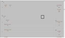
I have a jpg attached of part of John's stage program. Between 6 & & is the rung to initiate the timer, from what I see once CTO is done the CT0 done bit will only be enable for one scan...is it different in stage programming or did I miss something. If its not different what will make the timer complete its timing routine?

Personally I think a flow chart can be translated into ladder just as easy. I aint the sharpest knife in the drawer but made a fair attempt at creating a viable ladder from the original example flow chart.

bottlestage.jpg
 
Once X2 closes 6 times, counter CT0 turns on bit CT0. That bit will stay on until counter CT0 reset by contact C0.

I can and do write lots of good fast ladder code. Stages are just a method of grouping and controlling the code. Some time I have 2 rungs in a stage, sometimes 50.

One project I am updating right now is 450 lines with about 50 stages and if I had interlocked all those rungs, I would have a hell of a time editing. But I can make major revisions easily, even to large sections of the code I wrote over 2 years ago.

It's just a tool, powerful one. A power tool. Yeah, that's it! I just can't believe no one here but me is using it!

Happy a great Friday evening!

Deitz
 
John Deitz said:
CT0 reset by contact C0

I think that's where the confusion lies. I read Ron's text and THEN looked at the ladder. I saw C0, but thought it was CT0. What a difference a T makes... :D

beerchug

-Eric
 
I think John's program does what was requested except we discussed the fact that the timer is an external device...

Stage programming reminds me quite a bit of both Fanuc and Motoman's methods of programming. I used lots of "JUMP"s and "CALL"s in those programs. Maybe I should look into using stages. DirectSoft4 has some special tools for stage programming I believe.

An interesting variation regardless. Is it any wonder troubleshooting someone else's code is a PITA. You are always most comfortable with what you use the most. I like to use SET and RST and some people prefer to use parallel branches for latches.

I'm willing to bet that familiarity wins in Steve Bailey's poll about the most important features in choosing a PLC.

-AJ-
 
I wrote that before we learned the timer was external, and I was so frustrated that I couldn't post it graphically, I didn't update it. I later posted the zip file just to provide an example of stage programming. I never even checked it for errors. And now I got us way off topic. Sorry, alehander!

:confused:
 
Yikes.. you guys are loosing me. Stage programming? Maybe when the program size justifies it, as John said. Well, I've got all the hardware now - it's time to take 'er for a test fill. I'll be using a ladder diagram which uses bits and pieces from all 3 diagrams posted here (unless the authors ajbachhuber, rsdoran, John Deitz object) and borrows from postings in this thread. Thank you all very much for the help - if I become a PLC expert, I'll be sure to come back and contribute as much as you have.

One last question - I'm driving solenoid valves with PLC relays. As far as I can tell, I should get a considerable inductive voltage spike from my DC solenoid shutting off or powering up. I'd like to extend the relay life - what (if any) industrial devices are available to suppress this spike? In the past, I've simply placed a diode accross an inductor - the voltage spike then dissipates across the solenoid itself. This seems a little flimsy for an industrial application. Any suggestions?
 
Automation Direct recommended a Transient Voltage Suppressor to me to extend the life of my relays. "You can order TVS at DigiKey 1-800-344-4539 and get part number P6K30CAGICT-ND" (Quote is from AD)
 
PLC Ladder Diagram

Please anyone with some knowledge of putting together a ladder diagram with 12 inputs ( 8 standard 24 VDC and 4 fast 24 VDC.) and relay type outputs. It can be any type of machine.
 
PLC Ladder Diagram

Please anyone with some knowledge of putting together a ladder diagram with 12 inputs ( 8 standard 24 VDC and 4 fast 24 VDC.) and relay type outputs. It can be any type of machine. Email it to my address [email protected]. Please I need it by Monday, April 4th.
 
Raedawg said:
Please anyone with some knowledge of putting together a ladder diagram with 12 inputs ( 8 standard 24 VDC and 4 fast 24 VDC.) and relay type outputs. It can be any type of machine. Email it to my address [email protected]. Please I need it by Monday, April 4th.

I have some knowledge:


| X0 Y0
|---[ ]----------------------------[ SET ]
|
| X1 Y1
|---[ ]----------------------------[ SET ]
|
| X2 Y2
|---[ ]----------------------------[ SET ]
|
| X3 Y3
|---[ ]----------------------------[ SET ]
|
| X4 Y4
|---[ ]----------------------------[ SET ]
|
| X5 Y5
|---[ ]----------------------------[ SET ]
|
| X6 Y6
|---[ ]----------------------------[ SET ]
|
| X7 Y7
|---[ ]----------------------------[ SET ]
|
| X10 Y10
|---[ ]---------------------------[ SET ]
|
| X11 Y11
|---[ ]---------------------------[ SET ]
|
| X12 Y12
|---[ ]---------------------------[ SET ]
|
| X13 Y13
|---[ ]---------------------------[ SET ]
|
| X14 Y0 Y13
|---[ ]---------------------------[ RST ]
|
|-----------------------------------[ END ]


Was this general enough to answer your general request?
I'm not emailing it. I know I read this late thus, the late responce. The generalness of your request is a clue why you got no answers in the time frame you wanted.
 
Last edited:

Similar Topics

Hi, Do you guys provide flow diagrams for HMI screens with new systems? By this I mean a document outlining how the HMI moves from one screen...
Replies
4
Views
2,306
I'm wondering if anyone has encountered some decent software out there for documenting logic flow, particularly for control systems. Preferably...
Replies
11
Views
5,600
U
Hi, I'm a student and need to make a process flow diagram of a plc installation and have no idea what one looks like. Can anyone help? Also, I am...
Replies
4
Views
8,693
Hi Everyone, Does anyone know of a good resource describing how to generate a program flow diagram that can easily be interpreted into ladder...
Replies
1
Views
5,831
Hi Everyone, Does anyone know of a good resource describing how to generate a program flow diagram that can easily be interpreted into ladder...
Replies
2
Views
9,901
Back
Top Bottom