Further educating myself...

"even more so as it works better now than it did when running on the original plc/program"
How have you evaluated that your new program is more "betterah"

Through testing with the operator and my own experience of running it.

There were some odd occasions when the cycle would not finish correctly when the stop button was pressed, it might leave the last part uncut. It would also not stop at the correct point in the cycle when the printing foil ran out - it would merely stop, my version allows the whole cycle to complete before stopping.

We also now have a better HMI where the user can select the type of job by name instead of having to enter cut specs manually - choosing the job now sets the feed length, amount of cuts required and the length of time the delivery belt runs for.

Not perfect yet but definitely better, plus the fact that we now have full control over the program
 
So I would have something like:

The system sequence now would be:
State 0 - Off
State 1 - Manual
State 2 - Stamp
State 3 - Feed
State 4 - Stamp + Cut
State 5 - Feed + Cut
State 6 - Alarm

Stamp Sequence:
State 0 - Stamp is Up
State 1 - Stamp Moving Down
State 2 - Stamp is Down
State 3 - Stamp Press Time
State 4 - Stamp Moving Up

So if the system is in manual, pressing the Stamp PB would trigger the stamp sequence to occur. I would not let the system sequence change from Manual while the stamp is sequencing.

The challenge of doing this well begins with defining all of your states well. This is done on paper (or whiteboard) - and I spend a lot of time thinking through it. I write all of the states on the board and then draw arrows showing which states can transfer to other states. For instance, if the system is in manual, maybe I don't want the Stamp sequence to have any press time - just go down and right back up - I would have an arrow that goes from state 2 to state 4 under those conditions.

I generally make a program file for each state sequence and then a program file for outputs. If you setup your states properly, each output is simply driven by an OR statement for the various states that would require that output to be on.


I don't know your details, but that's the general gist of state programming.


Is it possible you could expand on that part with a sample of ladder please, I just need to find the way in, once I fully get the method I should be ok.

For instance, where you say "I generally make a program file for each state sequence", is a state sequence in my case Stamp - Feed - Cut OR is it merely the stamp or feed portion? Maybe I am not looking at the project in the correct way yet?

Many thanks
 
Last edited:
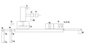
Just incase anyone wanted to step in and offer a direction for me to lean to, I have drawn a schematic using my very expensive CAD system :) And offer some info on the parts here:

Motors:
M1, M2 = Web tension
M3 = Foil rewinder
M4 = Main web drive
M5 = Delivery belt

Sensors:
S1 = Print head at BDC
S2 = Print foil sensor
S3,S4 = Feed 2 top/bottom limits
S5,S6 = Feed 1 top/bottom limits
S7,S8 = Cutter out/home

Valves:
V1 = Print power stroke
V2 = Print head lock at lower position
V3 = Print head advance/return
V4 = Cutter linear slide
V5 = Web clamp

That's about it really, the tension motors maintain the web tension via a rise/fall roller and linear transducers, limits detect a web break etc.

The print head is locked about 1" from the web when in auto mode, this shortens the stroke and saves much time on each stroke. Sensor S1 tells the PLC to apply the power stroke for a give dwell period.

The drive, M4 is a servo motor being driven by a stepper signal. Foil rewind M3 is running any time we are in auto.


;););)

PEELOFF1.jpg
 
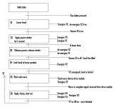
Am I heading in the right direction with my first try at SFC style coding or analysis at least???

The sketch attached would be for the simple style of process - stamp-feed-cut and not the Mk2 version where go stamp+cut - feed - stamp+cut. It would also be for the fully auto sequence option, I presume for the manual options I would have similar sequences rather than try and force one sequence to do all types - manual/auto etc??

Apologies for the quality of the drawings, I have nothing more than MS Paint here :)

It sort of makes sense to me, converting to ladder is another thing entirely but I need to get the start off in the right direction at least.:rolleyes:

PEELOFF2.jpg
 
Your state diagram looks okay, except it is lean on ways to stop the process. In reality, there should be a STOP connection from each state back to the Initial State 0 (Machine OFF). That is typical of most state diagrams - a lot is left out. It is those everybody-knows-they-are-there-so-why-show-them states that can hurt you.

If you can't stop it at any time, then never start it in the first place.
 
Last edited:
Your state diagram looks okay, except it is lean on ways to stop the process. In reality, there should be a STOP connection from each state back to the Initial State 0 (Machine OFF). That is typical of most state diagrams - a lot is left out. It is those everybody-knows-they-are-there-so-why-show-them states that can hurt you.

If you can't stop it at any time, then never start it in the first place.

Good point, none of the examples i've read show a stop point!

In reality, the safe, orderly stop point is where it loops back to S1, it should check if there is a stop request latched before looping in again.

Any other stop is really an e-stop whereby it can stop immediately regardless, this is controlled externally from the plc due to the power in use being dangerous. The plc gets a safety failed signal after the event.

At least I'm going in the right direction, what would be a suitable method of state control??
 
Hi glad your making progress. You can rol out this method down to individual sections of a machine that have a logical grouping. You can even go down to on/off staes if you want but I personally don't do that

For you I would probably have 5 general sequences

1 Semi Auto
2 Auto
3 Stamp
4 Cut
5 Feed

Each would have their own alarms, interlocks and resets but of course you may want a stop to complete the existing step....so I would call that a 'cycle stop' not a 'stop' .

The Semi Auto and Auto would have calls into and done flags linked to the stamp,cut and feed sequences

Hope that makes sense

I find it helps to get a sheet of grid paper and sketch out the sequence in sfc style before I write any code

Cheers
 
In reality, the safe, orderly stop point is where it loops back to S1, it should check if there is a stop request latched before looping in again.
The point was that state diagrams are supposed to show EVERY relevent state. As you see, the STOP state is probably the most important, though rarely shown. I think that is an unsafe practice right out of the starting gate. That is the big problem with state machine programs - rarley are all pertient states even idenfified.

It reminds me of what usually happens after an accident. Every involved person stands in the circle and points his finger at somebody else. "Not my fault that the machine was unsafe. I did my job, even though I assumed someone else would fix a way to stop the thing if things went bad. Didn't the Emergency Stop work?"

Using the E-Stop as a cop-out to allow you to do any darn thing you want to do is a poor practice. If every part of the machine has a way to stop it when things go wrong, then maybe at least one of them will work.
At least I'm going in the right direction, what would be a suitable method of state control??
One common method (and a good one because the State Number becomes the number that you use) is to set up a memory word location, named something like "Current State Value" or something similar. When the conditions for a state are met, then you move the state number into "Current State Value". Then the logic for each state looks for its value, and when true, performs all actions for that state. When a state is finished, the next state value is loaded into "Current State Value". This eliminates latches, unlatches, and seal-ins for each step.
 
Last edited:
Hi glad your making progress. You can rol out this method down to individual sections of a machine that have a logical grouping. You can even go down to on/off staes if you want but I personally don't do that

For you I would probably have 5 general sequences

1 Semi Auto
2 Auto
3 Stamp
4 Cut
5 Feed

Each would have their own alarms, interlocks and resets but of course you may want a stop to complete the existing step....so I would call that a 'cycle stop' not a 'stop' .

The Semi Auto and Auto would have calls into and done flags linked to the stamp,cut and feed sequences

Hope that makes sense

I find it helps to get a sheet of grid paper and sketch out the sequence in sfc style before I write any code

Cheers

Would each of those sequences be a collection of states? My guess is yes. If so would they be numbered sequentially even though they may never run in sequence, in other words, there is only ever one state "1" regardless of how many states the project has?

Just trying to grasp state control, in your example, semi-auto could have states 1-12, cut could have states 20-32 etc but each sequence would be a complete process on its own?
 
Ok, I have added a new state list, this time I think it shows the whole process.:whistle:

I have changed to text as I can type faster than messing around in Paint, hopefully it's clear, States are in bold, transitions are not.

Couple of queries, I have a conditional fork at S7-S1 transition, is that OK? Some jobs need 3 cuts per one impression so it loops the feed-cut states until the counter is done. It is at this stage where it checks for a stop request or a batch done is registered, this also stops it.

The pre checks at transition 0-1 where it tensions the webs, this is a sequence in its own right, so a separate set of states? It has to energise the lift motors then wait for up to 2 seconds, if the feed top/bottom sensors are not both clear after that period then a fault is logged and progress halted.

As for state control I would like a method where I can use XIC/XIO in the program rather than EQU/NEQ etc, I think it's clearer, there was an example earlier in this thread that should work I think.
 
I have attached a pdf of the first attempt at coding a transition sequence from my state list in the last post.

Not complete but am i going in the right direction and would it work??

This sequence is for the auto-run option.

The outputs are all in the main ladder as some of the output options will be used by other sequences, that seemed like the right place. They simply connect the various "state" contacts to various mapped outputs or counters, timers etc.


Thanks for the help BTW :)
 
Air Pressure Sensor?


It could have one fitted but not really needed, loss of air pressure does not create a danger situation, the head parks itself at BDC and all functions cease to have any effect.

Yes the head does drop under its own weight when air is removed, but having a sensor to alert the operator would not be able to avert that situation without some serious electro-mechanical alterations - blocking bars etc.

Due to the size of our air system, you would know something was wrong way before the pressure was low enough for the head to fall, its about 5psi to hold it up, we run at 6bar so a lot of air has to escape first, it's loud, very loud as we found out when a pipe split :whistle:
 
If this new style works in reality then I would be most impressed.

As I created the full auto sequence first, creating the manual sequence options is practically cut and paste :)

The proof will be in the pudding though.
 

Similar Topics

Hi all, I'm working on a project monitoring DLR rings using explicit messaging - (Citect SCADA ABCLX driver + 1765-L62 v20.19) Just a few...
Replies
3
Views
1,267
I'm looking online in a Project trying to catch a Jam instant. I'm looking at the Logic of this AOI where I found the only instant of a Jam Photo...
Replies
16
Views
5,325
Hello, I am looking for a product to help me better understand logic control systems. I have been working with Allen Bradley PLCs for about 3...
Replies
5
Views
2,477
Hello, I have a question on furthering my education and what you guys think would prepare me for the future in automation. I have a 2yr diploma in...
Replies
11
Views
4,658
hi, my names Ben. Ive recently been thrown into the deep end of plcprogramming at work for large specialised vehicles. i dont know too much...
Replies
3
Views
2,837
Back
Top Bottom