Ron said...
Wouldnt it be fair to say that under the conditions you implied/stated that a 6TH case is involved?
Turn it ON, Turn it OFF, Increase it, Decrease it, or do nothing.
OR DO SOMETHING?
The
act of turning something ON, OFF, Increasing or Decreasing
is doing something!
Your explanation stated this to be a vector, 3D or maybe more dimensional aspect of control. Wouldnt that imply that the options of move up, down, left, right, 20 degrees SE, 200 degrees NW etc etc are involved? Therefore the 6th case could be DO SOMETHING, move right, slow down, speed up etc etc al?
I have reread this several times and I know increase it/decrease it was stated but that alone doesnt cover(all)movement if its involved..at least I dont think it does. Maybe it could though but not sure, seems to me it would make more sense to state it using move, turn or direction but DO SOMETHING kind of covers it for me.
Sounds like you are talking about a "robot" using that "6-Degrees of Freedom" thing. What I am describing includes that and goes well beyond.
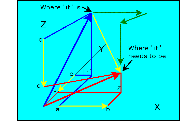
The figure below shows a 3-D, orthogonal map. There are three axis: X, Y and Z. Each axis can represent any factor under consideration… Position, Velocity, Acceleration, Color, Temperature, … whatever!
There is an indication (at the end of the Blue arrow) of Where "it" is at. The "it" is the thing, or process that you are trying to control. There is another indication (at the end of the Red arrow) of Where "it" needs to be.
The Red and Blue Arrows are Vectors. The Blue Vector indicates the "current conditions" of the "factors" (X, Y and Z). The Red Vector indicates the "desired conditions".
In this example, each Vector is comprised of three components: an X-Component, a Y-component and a Z-Component. There could be any number of components… of course, the more there are, the more difficult it is to envision.
The direction of each component is fixed along its particular axis. The magnitude of the components is determined by projecting the vector onto each of the three axis.
The Blue Vector: Starting at the origin…
the X-Component extends to "a"
the Y-Component extends to "e"
the Z-Component extends to "c"
The Red Vector: Starting at the origin…
the X-Component extends to "b"
the Y-Component extends to "f"
the Z-Component extends to "d"
Now, assuming that this is a "simple" model, that is, the shortest path between "where it is" and "where it wants to be" is the best, then the Yellow Vector represents what needs to happen to get from "here" to "there".
The Yellow Vector is no different from the Blue and Red Vectors… except, the Yellow Vector represents the difference between those two vectors. The Yellow Vector starts at "Where it is" and ends at "Where it needs to be".
The Yellow Vector is not determined by projection onto the axis… rather, it is the other way round.
The difference between the Blue-X-Component and the Red-X-Component is indicated by the Yellow Arrow, on the X-Axis, from "a" to "b".
The difference between the Blue-Y-Component and the Red-Y-Component is indicated by the Yellow Arrow, on the Y-Axis, from "e" to "f".
The difference between the Blue-Z-Component and the Red-Z-Component is indicated by the Yellow Arrow, on the Z-Axis, from "c" to "d".
The Yellow Arrows along each axis represent the changes required, in each factor, to "Vector" (verb-form) the "current condition" to the "desired condition".
The Yellow Vector:
The X-Component of the Yellow Vector starts at "a" and extends to "b"
The Y-Component of the Yellow Vector starts at "e" and extends to "f"
The Z-Component of the Yellow Vector starts at "c" and extends to "d"
Each component of the Yellow Vector represents changes that need to be made in the particular factors to bring the system where it needs to be. Now, each of those factors is controlled by something. Those controllers can be made to operate independently or dependently. If left to run independently, then the resulting vector could end up looking like the path shown by the Green Arrows. In this case, the system resolved the X-difference, then the Y-difference and then the Z-difference. This might not be acceptable, but then again, it might be… "It Depends"!
If it is necessary to follow the Yellow Vector, then you want to have the three controllers dependent on each other. That is, you don't want any one of the controllers getting away from the other two. Now… you could use three PID Controllers…
With Fuzzy, your code looks at all three factors and makes decisions for all three factors based on the rules that you create and the "weighing" (the Yellow Arrows on each Axis) of the difference between "Where it is" and "Where it needs to be".
It could very well be that you don't want the Yellow Vector to be a straight line… maybe you need a curve of some type. That too can be developed by establishing the proper rules.
This same model can be extended to include any number of factors. You don't have to put 20-factors in one model… you can just as easily have 5-models, each with 4-factors. Not all of the factors in a model have to be controlled by that particular model… it could be that one or two of the factors are only monitored for the sake of controlling others.
As always, you are limited only by your imagination.


