Ground loop problem

theripley

Member
Join Date
Jul 2008
Location
laguna
Posts
545
Hi,

Is ground loop problem on multiple current analog signals depend on the hardware (i.e. PLC) or on the signal generator (i.e. pressure transmitter)?

I have had an application before that requires me to use 4-ch AD module (in that case Mitsubishi) connecting 2 0-10Vdc (inverter) & 2 4-20mA (auxilliary out of temp controller & motorized pressure regulator). I have no problem with connecting the Vin but upon connecting 2 Ain, alas I had error on both device. I searched on what might be the cause & found out due to ground loop.

Another application I did using 2 Ain (2 pressure transmitter) was with keyence. I connected 2 4-20mA on the AD module but no apparent problem occur (hmmmm).

This leads me to ask the above question. Please help!
 
Confirm use isolators. It dpends on teh way the anaolgue input card is manufactured. I bet the inputs are loop powered - I always use isolators with loop powered inputs regadless of what brand of PLC I am using. Driven isolated outputs are a different kettle of fish and are usually OK without isolators.
 
It is a hardware problem in that it is usually related to the input impedance of channel. An isolation module takes care of this.

What is the ideal impedance (if there is) so I can be sure ground loop problem will not occur (& i will not be obliged to buy expensive signal isolators :()
 
Sometimes it depend where the return refference is connected to and for exemple 2 24vdc sources from 120ac using a TFO can have the both floating referrence where you would get a voltage potential and current at the module making the refference connection affecting the signal reading. To get rid of it, you need to hardwire both refference together.
The other exemple is when using very long cable and remote refference get above the good refference and shorting it create a voltage or current signal...Remote i/o using their own power supply can get rid of it
 
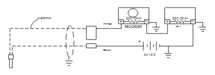
What I most often see referred to as a ground loop is caused by having two devices in the same loop that are tied to ground on one terminal. See the attached for an example of this type of loop. The current follows the path of least resistance, going to ground after the recorder and the signal never gets to the second device in the loop.

Using a signal isolator will take care of the problem. The loop goes in series through the isolator input side and one device. The output of the isolator goes to the other device.

In my experience the problem with impedence isn't a ground loop. If the impedence (sometimes called burden) is too high then the output signal doesn't have enough voltage to push the 20 mA signal current through the device. The maximum load is usually defined in the transmitter manufacturer's specs - 500 Ohm and 750 Ohm are common limits for 24 VDC loop powered transmtters, but you need to check.

ground loop.jpg
 
Last edited:
Ground loop is one of those phrases that gets used a lot but people don't always know exactly what it means. You have to ask where the ground in ground loop comes from. And remember that Ground is very different from Earth. If you don't ground one side of your 24V d.c. power supply, and none of the other devices in the signal loop are grounded, and all of the sensors are isolated from an Earth connection, you will never get a Ground Loop problem. But... from other discussions here you may know that unless you have a very good reason you should Ground one side of your power supply, and you can't guarantee that any other devices you use won't have a Ground, and I see way too many sensors and probes that aren't isolated. So there is a good chance that you will end up with two Grounds that are at slightly different potentials, different potentials means a current will flow, which then screws up 4-20mA signals. At the end of the day unless you can tie one side of all supplies and converters together with a zero ohm link, and only use isolated sensors, you are going to have problems and end up needing isolators.
 
Ground loop is one of those phrases that gets used a lot but people don't always know exactly what it means. You have to ask where the ground in ground loop comes from. And remember that Ground is very different from Earth. If you don't ground one side of your 24V d.c. power supply, and none of the other devices in the signal loop are grounded, and all of the sensors are isolated from an Earth connection, you will never get a Ground Loop problem. But... from other discussions here you may know that unless you have a very good reason you should Ground one side of your power supply, and you can't guarantee that any other devices you use won't have a Ground, and I see way too many sensors and probes that aren't isolated. So there is a good chance that you will end up with two Grounds that are at slightly different potentials, different potentials means a current will flow, which then screws up 4-20mA signals. At the end of the day unless you can tie one side of all supplies and converters together with a zero ohm link, and only use isolated sensors, you are going to have problems and end up needing isolators.

You meant to say "should not" right?
 
1) Impedance has little to do with ground loop problems, as Tom explained.

2) Analog input cards are market segmented like automobile tires: good, better and best.

The least expensive analog input cards are single ended, with a common return (-) for all channels, even if there's a separate screw terminal for a channel. These are the cards that cause the most problems.

People tend to pay attention to the A/D bits (10 or 12 or 16 or whatever) but only those of us who have been burned pay attention to isolation. It costs more to buy differential, isolated AI cards.

In some extreme cases, not even differential cards can handle the common mode or ground loop and require an external isolator.

3) My experience is exactly the opposite of BobB's. I have found that 2 wire, loop powered (passive) outputs/transmitters powered from the SAME floating power supply work without ground loop problems even with single ended AI cards.

4 wire devices (2 wire AO is 'active' output) powered from a "who knows where" power supply are the most problematic devices, almost always requiring an isolator, unless the device is powered off the same AC line as the PLC.

3 wire devices powered from a local power supply, may be a problem, may be not.
 
Hi Doug

Sorry, but I meant what I wrote, should be. In fact regs in Europe state that one side of a power supply shall be earthed, except in specific circumstances.
 
If you don't ground one side of your 24V d.c. power supply, and none of the other devices in the signal loop are grounded, and all of the sensors are isolated from an Earth connection, you will never get a Ground Loop problem.

I believe the "ground" you were referring to is the 0Vdc potential (common). If so, then I assume you were referring to a floating supply (please correct me).
 

Similar Topics

Hi all, I need to send a 4-20mA signal from a PLC (ICLinks Everest) to a paperless chart recorder (Endress and Hauser RSG30) and I'm having a...
Replies
7
Views
2,262
Hi everyone, as this is my first experience with Rockwell Software i would like to know what's the best way to make Enumerations?
Replies
10
Views
517
Hello i can not change one of the displays background color, the "Apply" button is greyed out. the firmware 5.10(older PV PLUS1000). I can change...
Replies
2
Views
1,208
We switched from a SLC5/04 to a 5069-L320ER, and the SLC's NI4's were replaced with the 5069-IY4, which is a pretty neat card; however, the IY4's...
Replies
3
Views
1,758
We have a 753, 75 HP, driving a centrifugal pump, that has been giving us ground faults for months. The drive has load, and line reactors. We have...
Replies
19
Views
8,485
Back
Top Bottom