Help Math reminder / calculating encoder cnts per unit

milmat1

Member
Join Date
Aug 2005
Location
North Carolina
Posts
209
This application has a motor with encoder feedback that drives a linear actuator that moves in/out, and is at roughly 45 degs from horiz.


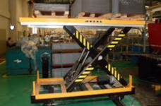
As the linear actuator moves in/out, it pushes a platform up and or down vertically, which is level with the horizontal. So movement is non-linear as related to the motor's rotation and linear actuator. Think of a motorized scissor lift.


If I know the counts at two points in the travel, and what they equal in vertical movement. How do I calculate the counts per inch of the lift. Or even revolutions per unit of vertical travel?
 
If the actuator moves along a 45º ramp

vertical movement = movement along the ramp * sin(45º)
 
https://en.wikipedia.org/wiki/Pythagorean_theorem


If instead of a linear ramp,

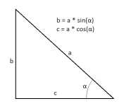
  • the distance b is the unknown vertical position of the platform, and
  • the distance a is a known constant, and
  • the linear actuator is changing the distance c in the image below,
  • so vertices ab and ca are fixed, and
  • vertex bc is fixed horizontally but not vertically,
then you want to use the Pythagorean theorem.
Pythagorean.svg

In an actual scissors lift, distance c and either vertex ab or ca would be fixed, and distance a would be changing, but solving for b would still use Pythagoras.
 
Also, the Count/Height pair at two values is not enough to characterize the relationship between Height and Counts.

You need either the horizontal distance a or a third Count/Height pair.
 

Let's say we Have three samples for counts (X) and corresponding heights (H):

Sample# 1 2 3
X 12500 22300 32500
H 140 252 360

Make a table of the following quantities (e.g. a spreadsheet)

H2
19600 63504 129600

H32 - H2
110000 66096 -

X3 - X
20000 10200 -

X2 - X1
9800 - -

X3 + X2
54800 -


Calculate the parameters m, k, and a:


m2 = ((H32 - H22) / (X3 - X2) - (H32 - H12) / (X3 - X1)) / (X2 - X1)

m2 = ((66096 / 10200) - (110000 / 20000)) / 9800

m2 = 0.0001

m = sqrt(m2) = sqrt(0.0001)

m = 0.01


k = (((H32 - H22) / (X3 - X2)) - (m2 * (X3 + X2))) / (2 * m)

k = ((66096 / 10200) - (0.012 * 54800)) / (2 * 0.01)

k = 50


a2 = (m * X + k)2 - H2

a2 = (0.01 * 32500 + 50)2 - 3602

a2 = 11025

a = sqrt(a2) = sqrt(11025)

a = 105


So, for any count value X, and parameters m, k, and a:


  • the model for height is

H = sqrt((m * X + k)2 - a2)


  • the model for actuator length, L, is

L = m * X + k


  • The model for change in height per count is

dH/dX = m * L / H


Last edited:
I should say that three samples is a minimum, and the spread of the samples across the operating range should be as large as possible (two ends and near the middle, and that even so your model is a slave to any errors in those samples' measurements. A better approach would be to fit a model to many samples to beat down the noise.

Also, a straightforward linear segment model with near-regular samples might be accurate enough, and not require square root or any other voodoo.
 
I would like to see a picture. It seems to me one could calculate the formula for height vs linear actuator motion. If I were doing tech support for one of our motion controllers, I would say either figure out the formula OR plot the height vs linear actuator position. start all the way retracted and note the height, then extend the actuator 1 inch and recored the height. Repeat until fully extended. The enter this data into a spline/cam table. BTW, you need to have the height on the X axis and the linear position on the y axis. If it were one of our controllers you could now enter the height, rate of change in height and the controller would translate it in to linear position and linear position velocity.
The motion would be smooth and accurate.
 
The math is the easy part, but as @Peter Nachtwey notes we still do not have a definitive idea of what the geometry of this system looks like. Typical thread, I guess.

The interesting bit is putting it into the PLC or whatever controller is positioning the actuator. If that device has a square root function, or trig functions, or it can model splines, then it may be fairly trivial. If not, ...
 
Last edited:
I would have had this solved in a few moments....without math!

This application doesn't look similar, but it is solved in a similar way. Both applications want to control the position of something but the relationship to the linear actuator is nonlinear. In the video the student is using commands that specify the angle, rotational speed and acceleration to move from one point to another. The OP want to control the height of the platform and I assume the speed and acceleration getting there so the OP wants to issue commands in height in inches. The trick is to map rotational position in degrees or height in inches to linear positions. To do that we use curves/splines/cam tables whatever you want to call them.

In the video the student shows he can do that in about 15 minutes after training. Notice the motion is smooth no matter what the angle. The student gave a command in degrees and it got translated into linear actuator positions. We use the chain rule ( remember that? ) to translate rotational position, velocity and acceleration into linear position, velocity and acceleration. We also update the 7 gains every millisecond as a function of the swing arm angle. So the swing arm tuning is adjusted all the time. The gains need to change a lot as the swing arm goes over top dead center.
Many people on this forum have been to our advanced training.

https://deltamotion.com/peter/Videos/Non-Linear-Lab_Medium.mp4

More details.
https://deltamotion.com/peter/Videos/Swing Arm.mp4

So it is possible to issue position, velocity and acceleration commands to the scissor lift in inches and translate those commands into linear actuator position, velocity and acceleration commands.

In the real world I HAVE NEVER seen the manufacturer provide the mathematical relationship between what you want to control and the linear actuator. A thousand curses on mechanical engineers that design **** without thoughts on how it is to be controlled. So I used my mathematic to enable customers to do this without knowing much more than how to scale the devices.
 
do modern PLCs typically have arccos? Logix and S7 and Do-More do; Click might not.

And OP still needs to solve for m, k and a.
 
Last edited:
You all are assuming the angle between the linear actuator and the ground or bottom frame is constant. It won't be.

Whether the PLC has the right math functions is just a secondary problem. The real problem is that the programmer can't figure out the formulas! Isn't it obvious that the angle relative to the ground changes as the linear actuator extends and contracts.?

Look at my second video. You can see the linear actuator doesn't stay at the same angle to the ground as it pushes the small end of the swing arm.

This gets back to tinine's derogatory comments about the RMC last summer. I wonder if his Galil or Trio controllers can to what an RMC or if he has the mathemagic to solve this problem.

@OP, the counts per inch will always be changing as the linear actuator extends and retracts.
 
You all are assuming the angle between the linear actuator and the ground or bottom frame is constant.


Um, well, no, actually. If this was not the case then the system would likely be linear and the thread would never have been started.

To be fair, we have nothing but OP's first post as a definitive spec to go on, and we have various assumptions beyond that. That said, the models proposed definitely assume that the angle of the centerline of the linear actuator does indeed change.

In my model the platform is constrained to move vertically only, which constraint was specified by OP in Post #1. That is probably not strictly true, but it is also probably close enough; if we don't make that assumption then we also have to start considering pin and joint deformations as the loads change.
 
Um, well, no, actually. If this was not the case then the system would likely be linear and the thread would never have been started.
I would like to see an example. Your picture of a scissors lift is not linear. Close but not quite.

To be fair, we have nothing but OP's first post as a definitive spec to go on, and we have various assumptions beyond that. That said, the models proposed definitely assume that the angle of the centerline of the linear actuator does indeed change.
Yes.

In my model the platform is constrained to move vertically only, which constraint was specified by OP in Post #1. That is probably not strictly true, but it is also probably close enough; if we don't make that assumption then we also have to start considering pin and joint deformations as the loads change.
how can it move vertically only if the scissors are extended. The top and bottom of the scissors become more narrow as the scissor extend? It looks like the right side of the scissor in your picture is fixed.
 

Similar Topics

Hello - you folks were kind in helping me the other day so I'm back for more... My program is finished however the end customer hasn't provided...
Replies
4
Views
1,937
Hey guys, I have MLX LOGIX1400 running fine except that it faults sometimes on math over flow. I examined the program and spotted a...
Replies
8
Views
2,325
Hey guys, I'm programming this stepper motor to go back and forth at two set angles. After programming, I realized that my program only works when...
Replies
8
Views
2,286
Hello all, I am trying to synchronize the speed of two motors so that once an operator sets them both where they want they can push a button that...
Replies
4
Views
2,713
I am taking a Simple SP which is in BCD and adding to that, When doing so I have noticed if the value is < 8 it works out fine, but if > 8 it...
Replies
4
Views
2,492
Back
Top Bottom