Help with timer/counter programming RX3i PME

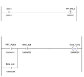
For example, consider these two rungs:
FD32948C-4E0A-4987-96FE-19B42BBE3DFE.png
  1. The value of time_out cannot be simultaneously
    1. BOTH 1 on the lower branch NOCON (Normally Open CONtact),
    2. AND 0 on the NCCON (Normally Closed CONtact) after the branches rejoin.,
    3. so the NOCON time_out and the lower branch can be removed, because it can never affect the output.
  2. Furthermore, the first rung shows that PTT_PULSE is a one-shot i.e.
    1. PTT_PULSE's value is 1 when the push button, I00013, has a rising edge,
    2. PTT_PULSE's value is 1 for at most one scan cycle
  3. For any scan when PTT_PULSE's value is 1,
    1. the value of I00013 must have been 0 on the previous scan cycle
  4. Therefore, if the PPT_PULSE value is 1, then the time_out bit's value cannot be 1 and must be 0,
    1. because the time_out value can be 1 only when the button is stuck
    2. i.e. when the value of I00013 has been 1 for at least the previous 15s of scan cycles,
    3. but we know that I00013 was 0 on the previous scan cycle.
  5. So if the PPT_PULSE value is 1, then
    1. The NOCON PTT_PULSE instruction must evaluate to TRUE,
    2. and the NCCON time_out instruction must evaluate to TRUE, because the time_out value is 0,
  6. And if the PPT_PULSE value is 0, then
    1. The NOCON PTT_PULSE instruction must evaluate to FALSE,
    2. so the value of time_out does not matter
  7. So the NCCON time_out instruction can be removed, because it can never affect the output.
    1. so the NCCON time_out instruction can be removed, because it can never affect the output.
Also, why is the value of time_out being evaluated on a rung that uses the SET instruction to only assign the value of Start_Pump to 1, and that rung cannot assign the value of Start_Pump to 0? If the button is stuck so that the value of time_out is 1, that should cause the program to stop the motor i.e. to assign the value of Start_Pump to 0.

This is what I am mean when I say the rungs are not much different than random guesswork: they may work, but they are confusing.
 
Finally, these functionally-related but visually separated, and therefore harder-to-read rungs:
Untitled.png
Would be much cleaner like the image below.

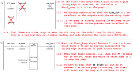
Although, to be fair, using the SET/RESET (SM/RM) scheme is equally valid, as long as those rungs are next to each other, and the NOCON PTT_PULS SM Start_Pump rung would be much simpler.
Untitled2.png
 
(1) What is meant by "the push button must be a (PT)?"

(2) Since we are detecting single edge events (rising edge of the push button input signal; as @Steve Bailey notes this is typical built in to counters), electro-mechanical "bouncing" of the physical push buttons internal could cause a problem. That is, the operator pushes the button once, to add 240s, once, to the delay timer, but the PLC, running scan cycles at 100Hz to 1kHz speeds, detects more than one rising edge of the electrical input signal for the single physical press by the operator. I mentioned debouncing the push button input signal a quarter century of posts ago, assuming OP would know what I was talking about and how to deal with it. If that is not the case, then see here.

(3) I do not mean this in a demeaning way, but when I look at these latest screen dumps of the code, I doubt OP could tell me either (i) what each rung is doing or (ii) where each rung fits into the grand scheme of the PLC model of the system; in other words, it works but OP probably has no idea why. @Steve Bailey provided an example of what I am all but certain is working code; I did the same and even tested it on a similar system. The code I see in these images may be related to the problem at hand, but it looks nothing like what @Steve Bailey or I provided, and looks more like random guesswork. Not only that, even if it works I do not see how it can be cleaned up to the point where someone troubleshooting this system, when the push button or discrete input channel fails, will be able to easily diagnose what is happening in a reasonable amount of time, and that is the most important aspect of any PLC code. Again, I am not trying to insult anyone here; OP stated at the beginning that they had little experience programming, and all I am saying is that I have seen no evidence to the contrary. Cries of "but it works!" now will mean little when OP is troubleshooting the system at 3am or with management anxiously and/or angrily watching over their shoulder.

(3.1) Try duplicating @Steve Bailey's code; that code's logic has a very simple progression, has simple and brief, but descriptive, comments, and is easily understood.

(3.2) If some piece of hardware fails in the future OP will be able to look at this code in online mode and easily follow the logic and deduce the nature of the failure; that is money in the bank.

(3.3) If the duplicated code does not work, then post screen dumps of it so we can check if it accurately reproduces the original code, and please also describe the symptoms of how it does not work.

(4) I assume this is not a homework assignment.


Just to come back to your response without going all-in. as I said before. I am not a programmer. I tested what Steve sent me and the counter does not start and nothing happens, see the photos below. can you explain to me what i did wrong? I took everything literally. furthermore, this is not a school assignment. I’m not at school. I won't go into too much detail about the rest. Let's first look at Steve's code and see what I did wrong there. because the counter does not start. As soon as I release the push button the engine turns off again. so I assume engine start should be a (set m). But doesn't this also have to be reset? where does that happen?

598E5AA6-1258-4A30-A1AA-7D52D93465AA.jpeg 31C85E71-2308-41A3-8682-80B0B76BFDD3.jpeg 09957373-C712-4B99-BBF8-B6D35CDB0268.jpeg CA782523-F315-4635-BCCF-5AF2F4170C74.jpeg 7979DF94-F247-46EC-B0C9-B2CBBA1E09B9.jpeg
 
Finally, these functionally-related but visually separated, and therefore harder-to-read rungs:Would be much cleaner like the image below.

Although, to be fair, using the SET/RESET (SM/RM) scheme is equally valid, as long as those rungs are next to each other, and the NOCON PTT_PULS SM Start_Pump rung would be much simpler.

I will adjust and test all this in the coming week. thanks for your comment. I will come back to this after I have adjusted everything.
 
In rung 4, I'm not sure what you did, but it appears you have created a variable apart from the three elements of the timer address. The output of the MUL_INT instruction is directed to a variable named "Duration_Timer(1)" which has an address of %R10227. The second of the three addresses for the duration timer should be %R10228. Try opening the variable list and dragging the second element of the "Duration_Timer" to the output of the MUL_INT instruction.

And note that since you used a TMR_TENTHS instruction your run duration will be 24 seconds, not 240 seconds.
 
Your original intent to have a 'stuck pushbutton' test is a good idea. In the logic I suggested, if the "Pushbutton_Input" bit is still true when the duration timer times out, the action will get a bit squirrely since the counter will be reset to zero, resulting in a preset of zero for the duration timer.
 
Let's first look at Steve's code and see what I did wrong there.
CA782523-F315-4635-BCCF-5AF2F4170C74.png
As noted, there was a typo in duplicating @Steve Bailey's code (Andor.pdf; attached again here for convenience).

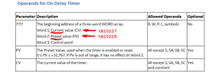
  • The MUL_INT instruction is modifying %R10227, which is the first word of the timer data words.
  • That first word (Word 1 in the image below) is the Current Value of the timer.
  • On the first scan cycle after the push button is pressed,
    • the motor starts (Rung 1),
    • the UPCTR increments to 1 (Rung 2),
    • and the MUL_INT (Rung 4) writes 240 to %R10227.
    • That %R10227 value of 240 for the timer's Current Value (CV) will be greater than the %R10228 value of 0 for the timer's Preset Value (PV),
      • so the timer will expire immediately,
      • which assigns a value of 1 to the boolean time_out bit %M04088
  • On the second (i.e. next) scan cycle, since time_out %M4088 has a value of 1 from the previous scan,
    • the NCCON (Normally Closed Contact) instruction of Rung 1 evaluates to True on its output rung
      • which causes the coil to write a 0 to Start_Pump, i.e. stopping the pump
    • the second NOCON (Normally Open Contact) instruction on Rung 2, which is feeding the R (Reset) pin of the UPCTR, evaluates to True on its output rung,
      • and the True state of that NOCON output rung resets the UPCTR to 0,
    • Since the UPCTR is now 0, the MUL_INT writes a value of 0 to %R10227 on Rung 4
    • So when the timer executes on Rung 5,
      • the CV's value of 0 is no longer greater than the PV's value of 0,
      • so the timer is no longer expired,
      • so time_out's value will become 0
  • On the third scan cycle, and all scan cycles after that as long as the push button remains pressed, since time_out's value is 0 and the push button is still pressed,
    • Rung 1 writes a value of 1 to Start_Pump, starting the pump again
    • Also, the Pushbutton_input value remains at 1, so it does not have a rising edge and does not increment the UPCTR again,
    • Finally, the timer remains un-expired, so the value of time_out remains at 0.
The motor starts, stops, and starts again, and the UPCTR increments and resets, so quickly during those first few scan cycles after a push button press that we will almost never see those intermediate values change in online mode, which made it appear to @Andor that the counter never incremented, when in fact it actually did increment to 1 and then immediately reset to 0 before the online mode could capture the 1.

Untitled.png
 

Similar Topics

Hello every one. I am just beginning with Proface and have no clue how it works. I have read the help section but still im not getting very far...
Replies
2
Views
2,454
Hello my name is Dorrance I am very new to plc programming. I am capable to make simple programs like inputs that trigger outputs but never worked...
Replies
11
Views
3,832
Hi all, This is actually a personal project, if that's ok. My uncle has some property that has a well, he wants to have the well automatically...
Replies
7
Views
2,493
Hi there, I am accustomed to working with Logix 500 but have a program modification I need to do on a CompactLogix.... I created a timer...no...
Replies
7
Views
2,454
I have a conveyor whose speed varies between 20 and 50Hz through a PLC (HMI). I need to program a code with a timer whose value will vary between...
Replies
26
Views
4,428
Back
Top Bottom