Help with timer/counter programming RX3i PME

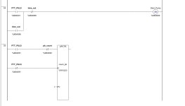
Simplify:Explanation: there is no need to use an extra rung testing for a value of 0 in the PUSH_BUTTON bit to reset the value of BUTTON_FAILURE to 0, because whenever the PUSH_BUTTON value is 0 the output rung of the timer will be FALSE, so we can use that instead.

In other words, the desired behavior, that the BUTTON_FAILURE value transitions from 0 to 1 ("on") with a 15s (150ds) delay after the PUSH_BUTTON becomes and stays 1 (i.e. push button is "stuck"), is exactly what how the input and output rungs of the Timer ON-delay (TON) instruction behave.

TL;DR

If the timer has expired because the push button was stuck and the PUSH_BUTTON bit value has been 1 for at least 15s so the BUTTON_FAILURE value is 1, and then the push button becomes un-stuck so the PUSH_BUTTON value changes to 0, then the timer's output rung will change from TRUE to FALSE, and the coil will write a value of 0 to BUTTON_FAILURE.

Also, if the timer begins timing but has not yet expired, then the timer's output rung will be FALSE, so the value of BUTTON_FAILURE will also be 0.

Only when the timer has expired, because the push button has been stuck for at least 15s, will the timer's output rung become TRUE, which will cause the coil to write a value of 1 to BUTTON_FAILURE.

The key point to remember is that a Coil instruction always writes something, either 1 or 0, to the value of its operand BUTTON_FAILURE, even if value being written is the same as the value of the operand before the Coil instruction executes.

sorry I forgot to mention that other programs are running in addition to this, and that if the push button is stuck, a message is sent to the HMI as a fault and everything is stopped for safety. something has gone wrong with the push button in the past.
 
The logic from the push button through the timer to running the pump should be no more than three or four rungs.


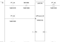
For example, that rung with the counter is doing nothing other than copying the value of PT_34 to PT_42 on each scan, so it can be eliminated and PT_42 replaced with PT_34 everywhere else.

I see, you're right. that's because the old program had a limitation. you could only press 1 time. the value %M01886 blocked the counter from counting multiple pressures while the pump was running. That is no longer necessary indeed. because now the pressure is added together.

97209AFC-B7D7-4EBE-BE85-21EF411989A1.jpeg
 
Here is my simple solution.


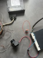
thank you, I want to test and monitor this with plc90-30 (363) and 1 input card and push button and 24v power supply that I still have lying around. how do I connect the power supply (+) to the button that then goes to an input A1 brown. where should the negative (-) be connected? does it go through the backplane or do I have to connect another cable from the input card to the blue (-) negative? see pictures

52F29702-81A4-48E2-9238-0516AB67B998.jpg 43949BB8-2B5E-4FCF-A8DB-A9D34CE97020.jpg
 
sorry I forgot to mention that other programs are running in addition to this, and that if the push button is stuck, a message is sent to the HMI as a fault and everything is stopped for safety. something has gone wrong with the push button in the past.


I understood that, I was only saying that there only needs to be one simple rung to implement that functionality, not two rungs (one for set, one for reset).
 
I see, you're right. that's because the old program had a limitation. you could only press 1 time. the value %M01886 blocked the counter from counting multiple pressures while the pump was running. That is no longer necessary indeed. because now the pressure is added together.


my point is that you do not need the UPCTR at all.


Once the [NOCON %M01886] has been removed, PT_34 and PT_42 will always be the same, so we don't need PT_42 and we can use PT_34 everywhere PT_42 is tested, and since we don't need PT_42, we don't need the UPCTR that writes PT_42.

Get rid of that rung with the UPCTR.
 
a message is sent to the HMI
Personally, since there is an HMI available, I would use that to set the pump's run duration rather than use a pushbutton. The HMI gives you a lot more functionality. You could show the preset run time as well as the time remaining. You could even decrease the run time if necessary.
 
I want to test and monitor this with plc90-30 (363)
The ladder I posted will work on the 90-30 CPU 363, except that variables in the 90-30 are address-based rather than tagname-based. The timer and counter will use three consecutive %R addresses. Be careful not to overlap the addresses when you program the functions.
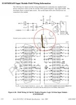
how do I connect the power supply (+) to the button that then goes to an input A1 brown. where should the negative (-) be connected? does it go through the backplane or do I have to connect another cable from the input card to the blue (-) negative?
You have the option of connecting an external power supply or using the built-in 24 VDC supply on the backplane which is available on terminals B6 and A7. Each group of 8 inputs can be wired as sourcing or sinking. Since you're using a contact closure for your input, sourcing or sinking is a matter of personal preference. If there are other devices already wired to inputs in the group, you'll need to match what is already present.
 
my point is that you do not need the UPCTR at all.


Once the [NOCON %M01886] has been removed, PT_34 and PT_42 will always be the same, so we don't need PT_42 and we can use PT_34 everywhere PT_42 is tested, and since we don't need PT_42, we don't need the UPCTR that writes PT_42.

Get rid of that rung with the UPCTR.

Thank you. programmer ever programmed it that way. I thought it was for something else. then i can take it out.
 
Personally, since there is an HMI available, I would use that to set the pump's run duration rather than use a pushbutton. The HMI gives you a lot more functionality. You could show the preset run time as well as the time remaining. You could even decrease the run time if necessary.

unfortunately we cannot place the hmi in the cold and outdoors due to water etc. a button is cheaper to replace. hmi is indeed easier. we have a quickpanel+ with lots of options. unfortunately this one is a bit too expensive to put outside.
 
Heh, starved ego indeed.

Comments left undone as an exercise.

I assume it will work, but it's untested.


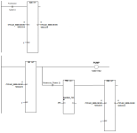
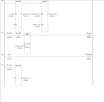
thank you very much for your help. I've put something together in the meantime. and it works. Steve's program stopped the timer for me. after that i made some changes and every time you press the button the timer starts again instead of continuing. I probably programmed something wrong. I spent half a day testing and programming on it yesterday. finally i have this below. I need to make it neat and simpler. But with a 90-30 363 ge fanuc and push button I tested it and it works. what struck me is that it is important that the push button must be a (PT). otherwise it counts double or sometimes more.

ED12893E-A922-4ACE-8B3F-7EF725882020.jpeg FD32948C-4E0A-4987-96FE-19B42BBE3DFE.jpeg
 
The ladder I posted will work on the 90-30 CPU 363, except that variables in the 90-30 are address-based rather than tagname-based. The timer and counter will use three consecutive %R addresses. Be careful not to overlap the addresses when you program the functions.

You have the option of connecting an external power supply or using the built-in 24 VDC supply on the backplane which is available on terminals B6 and A7. Each group of 8 inputs can be wired as sourcing or sinking. Since you're using a contact closure for your input, sourcing or sinking is a matter of personal preference. If there are other devices already wired to inputs in the group, you'll need to match what is already present.

thank you very much. I did it with an external power supply and it worked. I copied your program but the timer would not run. I personally think I did something wrong with the values ​​or the set and reset coil. I got to work and eventually (which took me half a day) I created a program that worked. I just have to make it neat. I added or removed something every time. which makes it a bit sloppy. see above in previous comment. thnak you for the help
 
... what struck me is that it is important that the push button must be a (PT). otherwise it counts double or sometimes more.


(1) What is meant by "the push button must be a (PT)?"

(2) Since we are detecting single edge events (rising edge of the push button input signal; as @Steve Bailey notes this is typical built in to counters), electro-mechanical "bouncing" of the physical push buttons internal could cause a problem. That is, the operator pushes the button once, to add 240s, once, to the delay timer, but the PLC, running scan cycles at 100Hz to 1kHz speeds, detects more than one rising edge of the electrical input signal for the single physical press by the operator. I mentioned debouncing the push button input signal a quarter century of posts ago, assuming OP would know what I was talking about and how to deal with it. If that is not the case, then see here.

(3) I do not mean this in a demeaning way, but when I look at these latest screen dumps of the code, I doubt OP could tell me either (i) what each rung is doing or (ii) where each rung fits into the grand scheme of the PLC model of the system; in other words, it works but OP probably has no idea why. @Steve Bailey provided an example of what I am all but certain is working code; I did the same and even tested it on a similar system. The code I see in these images may be related to the problem at hand, but it looks nothing like what @Steve Bailey or I provided, and looks more like random guesswork. Not only that, even if it works I do not see how it can be cleaned up to the point where someone troubleshooting this system, when the push button or discrete input channel fails, will be able to easily diagnose what is happening in a reasonable amount of time, and that is the most important aspect of any PLC code. Again, I am not trying to insult anyone here; OP stated at the beginning that they had little experience programming, and all I am saying is that I have seen no evidence to the contrary. Cries of "but it works!" now will mean little when OP is troubleshooting the system at 3am or with management anxiously and/or angrily watching over their shoulder.

(3.1) Try duplicating @Steve Bailey's code; that code's logic has a very simple progression, has simple and brief, but descriptive, comments, and is easily understood.

(3.2) If some piece of hardware fails in the future OP will be able to look at this code in online mode and easily follow the logic and deduce the nature of the failure; that is money in the bank.

(3.3) If the duplicated code does not work, then post screen dumps of it so we can check if it accurately reproduces the original code, and please also describe the symptoms of how it does not work.

(4) I assume this is not a homework assignment.
 

Similar Topics

Hello every one. I am just beginning with Proface and have no clue how it works. I have read the help section but still im not getting very far...
Replies
2
Views
2,454
Hello my name is Dorrance I am very new to plc programming. I am capable to make simple programs like inputs that trigger outputs but never worked...
Replies
11
Views
3,832
Hi all, This is actually a personal project, if that's ok. My uncle has some property that has a well, he wants to have the well automatically...
Replies
7
Views
2,493
Hi there, I am accustomed to working with Logix 500 but have a program modification I need to do on a CompactLogix.... I created a timer...no...
Replies
7
Views
2,454
I have a conveyor whose speed varies between 20 and 50Hz through a PLC (HMI). I need to program a code with a timer whose value will vary between...
Replies
26
Views
4,436
Back
Top Bottom