How does CLGX CMP real # to DINT

TStrong

Member
Join Date
Aug 2022
Location
Atlanta
Posts
5
Situation:
Single [EQU] instruction with single [OTE] on a rung, nothing else/simple. [EQU] operand(A) is a real number data type. Operand(B) is fixed value "0".

Result:
[EQU] sometimes executes as false when the value of the real number looks to be "0.0"

Question:
Does the CLGX execute the [EQU] in such a way that what I'm witnessing makes sense?

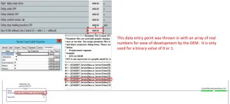
I'm probably going to move the real# into a DINT, then change the operand of the [EQU] to the DINT tag. This will work because the REAL# is being used by the OEM to reflect a binary state (interlock on/off). I think they just lumped this data into an array of real numbers where it didn't belong.
 
0) It should not matter, see here; bottom of page 817.

1) can you put 0.0 as SourceB, instead of 0? Not that I think it would make a difference.

Result:
[EQU] sometimes executes as false when the value of the real number looks to be "0.0"

Question:
Does the CLGX execute the [EQU] in such a way that what I'm witnessing makes sense?
Short answer: yes.

TL;DR

You are witnessing only a very small sub-sample of the hundreds or perhaps thousand of executions of that instruction per second. So

  • that SourceA value could change to a non-zero value for a few ms,
  • and the output rung would evaluate to False for all scans during those few ms,
  • and then the SourceA value could change back to zero,
  • and you would not witness the value of SourceA changing from 0.0 during that brief event, because there was no sub-sample of data displayed during those few ms.
The only way to have noticed would be if there was some persistent response to the False output rung state, which I assume is what has happened and why you are asking the question in the first place.

So, long answer: yes, if you consider more than just the execution of the instruction, and consider the nature of the subset of information that you witness.
 
0)

  • that SourceA value could change to a non-zero value for a few ms,
  • and the output rung would evaluate to False for all scans during those few ms,
  • and then the SourceA value could change back to zero,
  • and you would not witness the value of SourceA changing from 0.0 during that brief event, because there was no sub-sample of data displayed during those few ms.

Yes, I am familiar with the how the processor scans and the fact that there may be a small window of the scan surrounding the instruction in which the value changes from 0.0. Which would not be witnessed.

This is not the case. I could trend the data to confirm, but I'm pretty confident. The data comes from a panelview numeric entry.

To cure the issue I simply re-entered the value of "0.0" on the panelview. At which point the [EQU] executed as true.

There is no duplicate destructive bit, and the subroutine calls from the continuous task main program.
 
wow.

So you have a rung like this:

EQU real_val 0 OTE real_val_is_zero


that sometimes puts a value of 0 in real_val_is_zero when real_val displays as 0.0 in RSL/Studio 5000?

I would not bother with a trend; what happens if you add a rung

XIO real_val_is_zero CPS real_val non_zero_dint 1


right after that?
 
wow.

So you have a rung like this:

EQU real_val 0 OTE real_val_is_zero


that sometimes puts a value of 0 in real_val_is_zero when real_val displays as 0.0 in RSL/Studio 5000?

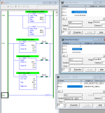
Exactly. I've attached an image to show validation of my claims.

wow.

I would not bother with a trend; what happens if you add a rung

XIO real_val_is_zero CPS real_val non_zero_dint 1


right after that?

This would capture the value as a DINT of "REAL_VAL" at the moment "REAL_VAL_IS_ZERO" = 0, without allowing the value to change before the instruction completes, correct? sounds like you still think that is whats happening, I can do something similar/exact to confirm.

The problem occurs once in a blue moon. likely after weekend maintenance when the machine was taken out of line control interlock state. So it may be weeks perhaps months until its witnessed again. And if im not here when it happens, someone with lesser knowledge has been modifying data in the wrong PLC (line control) to recover. This makes matters worse.

I can pretty easily change the P.V button to a momentary with a state indicator, and just latch/unlatch the [OTE]. Guess I was looking for a possibility that the processor stores REAL value in a format which would cause a false execution of the [EQU]

OEM_NTRLK_SLCT.JPG
 
0) It should not matter, see here; bottom of page 817

Found the problem reading this document you linked. The [EQU] converts source(B) from INT to REAL. The 1st bit of the 32 bit real number is the sign. the negative button on the HMI numeric entry is immediately next to the "0" button. I tested the theory by entering "-0" on the HMI. Sure enough it stored the negative sign for the REAL number, but still displayed it as "0.0" both in the PLC and on the HMI. Therefore my [EQU] was false because source(B) has no sign.

Thanks for the dialog..... helps get my thoughts together.

ISSUE_CAPTURED.JPG
 
You shouldn’t compare for absolute equality when dealing with floating-point types. Compare to a small range around the expected value instead and you’ll have more reliable results.
 
Originally Posted by drbitboy

I would not bother with a trend; what happens if you add a rung
Code:
[B]XIO real_val_is_zero [COLOR=Blue]CPS real_val non_zero_dint 1[/COLOR][/B]
right after that?
This would capture the value as a DINT of "REAL_VAL" at the moment "REAL_VAL_IS_ZERO" = 0, without allowing the value to change before the instruction completes, correct? sounds like you still think that is whats happening, I can do something similar/exact to confirm.

I tested the theory by entering "-0" on the HMI. Sure enough it stored the negative sign for the REAL number, but still displayed it as "0.0" both in the PLC and on the HMI.
:ROFLMAO:
So that suggestion, or something similar which I assume you did, would have found it? Nice work!

See item (i) below in my .signature.
 
IEEE754 has a dedicated sign bit unlike the implicit sign bit of two’s complement integers. In other words, the idea of a positive and negative value of zero are baked into reals.

Two’s complement integers replaced the one’s complement representation early on to ditch this possibility and be able to express the full range of possible values (2^n bits), which is why the magnitude of the most negative integer is always one higher than its most positive.
 
Last edited:
Code:
$ python

[B]    >>> import struct[/B]


[COLOR=Blue][B]### Demonstrate that -0.0 and +0.0 are different:[/B][/COLOR][B]

    >>> a,b=-0.0,+0.0
    >>> print((a,b,))
[/B][COLOR=Magenta][B]
    (-0.0, 0.0)[/B][/COLOR]
[COLOR=blue][B]

### Pack 'ff' (two 32-bit floating point i.e. REAL) values, -0.0 & +0.0, into a byte string,
### Then unpack those 64 bits as two 32-bit unsigned integers:[/B][/COLOR]
[B]
    >>> struct.unpack('II',struct.pack('ff',a,b))
[/B]
[COLOR=magenta][B]    (2147483648, 0)[/B][/COLOR]


[COLOR=blue][B]### Same thing, but display as hexadecimal:[/B][/COLOR]
[B]
    >>> list(map(hex,struct.unpack('II',struct.pack('ff',a,b)))[/B])

[COLOR=magenta][B]    ['0x80000000', '0x0'][/B][/COLOR]
Legend:

  • ### Description/comment
  • python statement
  • output of value returned by previous statement
 
:ROFLMAO:
So that suggestion, or something similar which I assume you did, would have found it? Nice work!

No, I just reasoned the cause by reading the document you linked about converting the integers, and how a real is stored. Thanks for that, and the dialog.

IEEE754 has a dedicated sign bit unlike the implicit sign bit of two’s complement integers. In other words, the idea of a positive and negative value of zero are baked into reals.

Two’s complement integers replaced the one’s complement representation early on to ditch this possibility and be able to express the full range of possible values (2^n bits), which is why the magnitude of the most negative integer is always one higher than its most positive.

Honestly, I had to read this twice to understand. The terms "two's compliment" and "one's compliment" I am not very familiar with, along with my new found IEEE754 term. But I understand your point, and thank you for sharing it.
 
Also, when I ran that on RSLogix Emulate 500, it would fault if there were less than four elements in Data File F8.

Two elements in F8 were adequate for the physical MicroLogix 1100 running the same program.
 
Might explain or complement the ability to manipulate real bits directly in earlier versions of 5k - they appear here to be forcing the sign bit to zero upon detecting the signed zero value.
 
Last edited:

Similar Topics

Hi, i am using DVP-14SS2 PLC, after program written to plc, when power is reset, plc doesn't run. always need to connect to pc for the run mode.
Replies
0
Views
14
I am trying to connect with a Schneider plc which has a firmware version only available in Somachine v4.2. In Machine expert After taking upload...
Replies
0
Views
112
They are installed in a control panel that was made in France and are intended for the termination of analog inputs. Each of the red capped...
Replies
4
Views
420
So, I'm really just trying to get some experience by practicing with arrays. I'm using studio 5000 v33. I have one rung with an XIC bit that's...
Replies
5
Views
239
Back
Top Bottom