How to Calculate Stepper Motor RPM from Encoder Pulses? - TwinCAT Beckhoff

GRANDMAST3R5

Member
Join Date
Mar 2024
Location
Gqeberha
Posts
7
Hi everyone,

This is my first time posting, so please forgive any omissions or mistakes.

I am attempting to control the velocity of a stepper motor to TEST my PID controller before applying it to a real system (on the real system, I am controlling a loading rate, measured in N/min, not velocity). The real system is delicate, and as I'm a beginner, I want to ensure that my PID controller operates effectively when it is decoupled.

I am trying to convert the encoder A input pulses to RPM for my feedback signal. Since the real system will be operating at speeds < 1 RPM, I have opted for a pulse timing method instead of attempting to measure a change in position. This decision was made because interrupt-based methods don't seem to be accurate at low speeds.

I am using an AS2023-0J10 Stepper Motor in conjunction with an EL7047 driver card. The stepper motor has an incremental encoder capable of providing 1024 increments per revolution. However, as it operates in quadrature mode, this effectively translates to 4096 increments per revolution. Nonetheless, tracking the A input pulse still results in 1024 increments, as it only signifies one of the four states in quadrature mode.

Could anyone provide guidance on how to go about calculating RPM from encoder pulses in TwinCAT3?
 
Hello GRANDMAST3R5 and welcome to the forum.

If you have the EL7047, and the AS2023 and wired correctly according to the documentation, all you need to do is setup the NC Axis stuff (also in the el70x7en.pdf). This lets you use TwinCAT to control the motion on that motor, and as long as your scaling parameter is set correctly, you can directly read the calculated Position and even velocity, the NC motion components will provide you a more accurate value for RPM than trying to calculate velocity of the same hardware in PLC code.

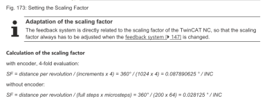
Default scaling of an Axis if I recall correctly, will be Rev/s. The manual pg 151 shows an example of how to calculate scaling for Degrees of rotation.
1710956487458.png

Sadly, I am much more concerned with the speed at which you want to spin the motor <1 rev/min, {and} the fact the encoder has only 4096 post quadrature pulses to deal with. That is a small number of pulses per unit time from which to derive velocity. I also do not know how well the drive manages the cogging torque of a stepper design. All these things lend themselves to velocity readings that "don't seem to be accurate at low speeds."

I am including links to the el70x7en for your reference should you opt to use the NC system.
el70x7en.pdf

Regards,
Patrick
 
Hello GRANDMAST3R5 and welcome to the forum.

If you have the EL7047, and the AS2023 and wired correctly according to the documentation, all you need to do is setup the NC Axis stuff (also in the el70x7en.pdf). This lets you use TwinCAT to control the motion on that motor, and as long as your scaling parameter is set correctly, you can directly read the calculated Position and even velocity, the NC motion components will provide you a more accurate value for RPM than trying to calculate velocity of the same hardware in PLC code.

Default scaling of an Axis if I recall correctly, will be Rev/s. The manual pg 151 shows an example of how to calculate scaling for Degrees of rotation.
View attachment 68899

Sadly, I am much more concerned with the speed at which you want to spin the motor <1 rev/min, {and} the fact the encoder has only 4096 post quadrature pulses to deal with. That is a small number of pulses per unit time from which to derive velocity. I also do not know how well the drive manages the cogging torque of a stepper design. All these things lend themselves to velocity readings that "don't seem to be accurate at low speeds."

I am including links to the el70x7en for your reference should you opt to use the NC system.
el70x7en.pdf

Regards,
Patrick
Hi Patrick


Thank you for your reply. I will try the NC system rather. Do you require any licenses to use an NC motion system in the runtime?
 
Do you require any licenses to use an NC motion system in the runtime?

Yes, when (or if) you are deploying to end-customer or out on production floor you will need to license the NC PTP component. This is similar to how you would need the PLC component to run plc code.

For bench testing and initial development you can simply use the unlimited 7-Day trial licenses for most features. You only need to license things when you deploy the system.

TC1250 is the TwinCAT3 PLC/NC PTP 10 combined package, includes both (TC1200 PLC, and TF5000 - 10 Axis NC PTP functions)
If you already have the TC1200 license just order the TF5000 to add the NC PTP functionality.
(links included above)


If you are using an actual Beckhoff Controller running TwinCAT 3, the cost to add on this license is generally affordable, and is always less than the cost of purchasing licenses for 3rd Party industrial pc's.

Regards,
Patrick
Thank you for your helpful suggestions. However, I need to clarify that I am implementing this controller on an existing system where the stepper motor is being added. Additionally, the end-user is unwilling to pay for additional licenses, as they are already utilizing a stepper motor and drive salvaged from another machine. Consequently, I will need to devise a method for determining motor RPM without spending any more money. Nevertheless, thank you for your time and effort in providing me with all this advice.
 
I will need to devise a method for determining motor RPM without spending any more money
So long as your time is free you might be able to do this...

You will have to pick a timeframe to update the rpm calculations. Basically RPM is just as it says, revolutions per minute. You probably don't want to wait a whole minute between updates so for example, if you can update your RPM calculations every second you could do something like this:

Run a task every second. This is much more accurate than running a 1 second timer that resets.
In this task:
  1. Calculate how many pulses have been logged since the last time the task ran. Usually you keep a variable with the number of counts the last time the task ran. Then you can do something like ELAPSED_COUNTS := CURRENT_COUNTS - LAST_COUNTS;
  2. Divide the ELAPSED_COUNTS by the task time. In this case 1 second.
    Assuming 4096 counts / rev
    RPM = (ELAPSED_COUNTS/4096) * 60 (sec/min)
  3. Save the CURRENT_COUNTS in the LAST_COUNTS tag.
You will have to be worried about how many counts go by between task runs. The tag for counts will roll over at some point depending on the size of the tag (16 BIT, 32 BIT). Generally, so long as you don't go more than half way through your accumulator/CURRENT_COUNTS (i.e. no more than 32767 counts for a 16 bit tag) then the integer math will work out to give you the proper ELAPSED_COUNTS.
Hi Norman

Thank you for the suggestion. However, if I'm not mistaken, isn't this method interrupt-based?
I would prefer a method based on the cycle time of the PLC. This way, I can quickly pass the feedback RPM to the PID controller every cycle, enabling smoother velocity control.

However, let's consider if I implement your suggested method and decide to change the interrupt execution to every millisecond (because I want my PID to work smoother). In such a case, how can I determine the minimum velocity at which I can set the motor without encountering a situation where a pulse fails to register because the motor is moving slowly, while the interrupt executes so rapidly that it produces a 'zero-RPM' reading?

That's why I was eluding to using a pulse period/timing method, where I would measure the period of a single pulse and calculate RPM based on the frequency (1/period). Do you know how to go about such a calculation or algorithm?

Thanks for your help.
 
At the end of the day you want revs (counts) over time. You can measure counts at a set time interval as I mentioned above. Or you can measure the time between counts and it’s basically the same thing.

If you measure the time of one pulse the
RPM=((1/4096)/(MEASURED_TIME_IN_SECONDS))*60

But you still need a very good /accurate speed reference. In this case you could try to set an interrupt on each encoder pulse and need a good way to calculate the time between pulses.
However if you don’t think you will get even one pulse in a scan sometimes then this number will jump likely jump around. As Zen said above, the low number of pulses is going to be a problem.

You mentioned that this is a test. What will the feedback be on the real application? Hopefully something like EnDat or Hiperface where you can get a high number of counts per rev….32 bits?…
 
The real application's feedback comes from a load cell. The motor regulates the speed at which a dead weight descends onto a test sample via a rod. My objective is to adjust the load rate (measured in Newtons per minute) by either slowing down or speeding up the motor until it reaches full load. This is why the motor operates so slow, as the distance from no load to full load is only 0.8 mm and it needs to be a controlled release.
 
I can quickly pass the feedback RPM to the PID controller every cycle, enabling smoother velocity control.

Passing the data to the PID faster than the PID updates does nothing; only the value available to the PID when the PID updates is used, and any past values are ignored.

A PID that operates on every scan cycle is probably misconfigured, unless that scan cycle is driven by a timer interrupt (e.g. every 100ms).
 
Maybe you are over thinking this. How many steps per mm do to have. If the actuator goes too fast, put a gearbox between the motor and actuator. Then even when the motor is going fast the linear speed is low. Do you really need to control N/mm or just to apply the load slowly?
 
Maybe you are over thinking this. How many steps per mm do to have. If the actuator goes too fast, put a gearbox between the motor and actuator. Then even when the motor is going fast the linear speed is low. Do you really need to control N/mm or just to apply the load slowly?
Hi nOrM

At present, I have the motor set to 1/8 step (I am going to move to 1/32 when testing). Additionally, there's a 10:1 gearbox in place (10 revolutions of the motor translate to 1 revolution of the output shaft). This output shaft is connected to a screw with a 1 mm pitch. Consequently, for every 1 rpm on the output shaft, there's a corresponding 1 mm/min movement of the dead weight. In any case, here is the code I've tested so far, as you said the value jumps erratically:

fbGetSystemTime(timeLoDW => tCurrentTime.dwLowDateTime, timeHiDW=>tCurrentTime.dwHighDateTime );
sCurrentTime := SYSTEMTIME_TO_STRING( FILETIME_TO_SYSTEMTIME( tCurrentTime ) );
FindAndSplitChar(':',ADR(Global_Variables.sCurrentTime),ADR(Global_Variables.sTodayDate),32,ADR(sTime),32,TRUE);

rTrig(CLK := Interfacing_Variables.bPulseA);
fTrig(CLK := Interfacing_Variables.bPulseA);

IF (rTrig.Q = TRUE) THEN
Global_Variables.bTrigger := TRUE;
Global_Variables.iCountT := Global_Variables.iCountT + 1;
IF(Global_Variables.iCountT = 1) THEN
Global_Variables.fPrevPulseTime := STRING_TO_LREAL(sTime);
END_IF
IF (Global_Variables.iCountT = 2) THEN
Global_Variables.fCurPulseTime := STRING_TO_LREAL(sTime);
Global_Variables.fdeltaTime := Global_Variables.fCurPulseTime - Global_Variables.fPrevPulseTime;
Global_Variables.fRpm := ((1.0/1024.0)/(Global_Variables.fdeltaTime))*60;//(2.0*PI*(1.0/ABS(Global_Variables.fdeltaTime)))/1024.0;
Global_Variables.iCountT := 0;
END_IF
END_IF
 
What is your scan cycle time? what is the resolution of the system time? If you are getting 1024 pulses per revolution, and running at around 1RPM, then you are getting as many as 17 pulses per second or so, which is around 60ms pulse length. If the scan cycle time is a few ms, then aliasing of the system time sample caused by the scan cycle time may have a significant effect on the measured duration of the pulse.

Maybe a better approach would be to use the rising edge of the pulse to trigger an interrupt routine that writes the system time of the interrupt to Global_Variable.fCurPulseTime, and then the program in the continuous scan looks for changes between that value and Global_Variables.fPrevPulseTime.

As it is, the code below only measures every other pair of pulse rising edges, if I am groking it correctly.
Code:
fbGetSystemTime(timeLoDW    =>    tCurrentTime.dwLowDateTime, timeHiDW=>tCurrentTime.dwHighDateTime );
sCurrentTime := SYSTEMTIME_TO_STRING( FILETIME_TO_SYSTEMTIME( tCurrentTime ) );
FindAndSplitChar(':',ADR(Global_Variables.sCurrentTime),ADR(Global_Variables.sTodayDate),32,ADR(sTime),32,TRUE);

rTrig(CLK := Interfacing_Variables.bPulseA);
fTrig(CLK := Interfacing_Variables.bPulseA);

IF (rTrig.Q = TRUE) THEN
  Global_Variables.bTrigger := TRUE;
  Global_Variables.iCountT := Global_Variables.iCountT + 1;
  IF(Global_Variables.iCountT = 1) THEN
    Global_Variables.fPrevPulseTime := STRING_TO_LREAL(sTime);
  END_IF
  IF (Global_Variables.iCountT = 2) THEN
    Global_Variables.fCurPulseTime := STRING_TO_LREAL(sTime);
    Global_Variables.fdeltaTime := Global_Variables.fCurPulseTime - Global_Variables.fPrevPulseTime;
    Global_Variables.fRpm := ((1.0/1024.0)/(Global_Variables.fdeltaTime))*60;//(2.0*PI*(1.0/ABS(Global_Variables.fdeltaTime)))/1024.0;
    Global_Variables.iCountT := 0;
  END_IF
END_IF

Also, you use the F_GetSystemTime to get a timestamp with 100ns (1E-7s) resolution.

So your code might look something like this:
Code:
(* ********* Interrupt routine, triggered on rising edge of pulse *************)
ulint64_currTimestamp100ns = F_GetSystemTime();

Code:
(* ********* Main routine ************** *)
IF ulint64_currTimestamp100ns > ulint64_prevTimestamp100ns THEN
  lreal_rpm = (60e7 / 1024.0) / ULINT_TO_REAL(ulint64_currTimestamp100ns - ulint64_prevTimestamp100ns);
END_IF;
ulint64_prevTimestamp100ns = ulint64_currTimestamp100ns;

It looks like there is also a timing function FB_SimPastCpuCounterTicks here, with 100ns resolution that makes it even simpler than that, although it returns two signed DWORDs that might require some additional fiddling.
The scan cycle is 1 ms, and the resolution of the system time is in multiples of 100 ns. In my code, I'm attempting to measure the time between two rising edges, as this represents the duration it took for the encoder to increment once, if my understanding of encoders is correct. Essentially, I'm aiming to capture the period between two pulses, but I see now it will miss every other pulse. I'll try your suggested method. Thank you.
 
Last edited:
I may be missing something here but Stepper motors are synchronous so if you ask it to do x steps/second then that is what they will do unless you hit pull out torque?

As for counting encoder pules to evaluate velocity, I have done similar in Siemens systems by using an encoder card designed for the high speed signals tghen poll it with a timed interrupt (10mS?) and calculate the number of pulses that changed in the time period. The accuracy of this will be governed by the pulse rate over the time period.

Trying to accurately evaluate the time between two rising edges is problematic because it will depend on the response rate of the input card, underlying I/O system and the execution of the program.

I'm not quite sure why you would need a PID loop to control the velocity of a synchronous device but, as others have said, don't execute a PID loop faster than the input variable can change or you will process the same error more than once which will result in over-integrating which, in turn, will give you an inherantly unstable system.
 

Similar Topics

Good morning, I have a question. I don't know much about ST yet I would like to calculate the average number of products per hour. how do I do...
Replies
22
Views
2,964
Can someone help me with this? I'm no good at SCL - virtually everything I've done so far has been ladder logic. The return value from the...
Replies
13
Views
1,107
I want to calculate the energy consumed from instantaneous power. Can this be done using the TOT block with timebase set to Hour?
Replies
2
Views
691
Hi everyone, I have to calculate the length in millimeters of a glass that enters a transport (I don't know the speed yet) through a barrier...
Replies
15
Views
3,465
I have a pump with ON off status in PLC micrologix 1400 my question is how I can calculate working hours base on ON/off status How I can use the...
Replies
5
Views
2,423
Back
Top Bottom