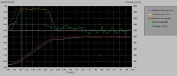
I have a project where I need to use a proportional valve to control hydraulic system.
Before, I used open loop and now I try closed loop PID with feedforward velocity and acceleration.
In open loop the maxim velocity depends with load, in closed loop this is ok. But in closed loop take some time to find stop position.
The accuracy of stop position is +7 mm maxim, ok for me.
In my PLC I writing a simple trapezoidal trajectory generator and I use feedback position PID control with feedforword velocity
and acceleration.
My loop is:
PLC Modicon M340 Schneider with time execution code 5 ms
analog output 0-10V, update 1 ms
proportional Valve 4WRKE Rexroth https://www.boschrexroth.com/ics/content/UpToDate/PDF/re29075_2013-08.pdf
hose size DN 16, hose lenght aprox. 4 m between proportional valve and cylinder
cylinder Area 1=31 cm^2, Area 2 = 15 cm^2, stroke aprox. 1 m, (flow 70 l/min, presure 120 bar)
load 100 to 300 kg
feedback position is rotary encoder XCC3510PS84CBN and bus Can Open update 2 ms with system resolution 2 count / mm
I have attached a plot. Some problems I have with my system tuning:
The system has dead time and can't track very well position.
1) For different stroke the system needs readjusting parameters for optimal settlig time.
I use Velocity feedforward , Proportional, Deadband and little Acceleration feedforward .
I've tried to use Integral term for reduced settling time, but Integral needs readjusting with stroke. I don t use Derivativ.
Any suggestion ?
2) The system has need different gains for Acceleration feedforward and Deceleration feedforward?
Any ideas what can be improved? I would appreciate any help with this issue.
Thanks in advance!

Attachments
Last edited:


