In and Out Solenoid Program

AP123

Member
Join Date
Nov 2023
Location
USA
Posts
4
Hello all, I am a beginner and am requesting some help. I have been tasked with a program in ladder logic where once the start button is pressed, the pneumatic solenoid must fully extend, then fully retract, forever, until the stop button is pushed, and the ON light is present the entire time its running.
There is a sensor that lets you know once it has reached full extension and likewise for retraction.


There are two issues I am facing in my various attempts at this program, one being both outputs come on at the same times, making the cylinder extend/retract slowly. If I correct that, the other issue is if the piston is in the middle, and neither sensor is activated letting the program know if its in the extended or retracted position, it will not start. So it needs to be able to start from any position.


I have spent a long time on this, and really hate to ask for assistance but I need to understand what I am doing wrong so I can become better. I appreciate it so much thank you all.
 
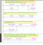
Try this, it is assumed that the solenoid is 5 port type i.e. the solenoids only need a pulse to move position so once triggered will go to position, if the solenoid is not this type just remove the reverse sensor in the last rung so it maintains the reverse solenoid. There are a number of ways to do this, so I bet you will get many ideas (Assuming I interpret your post correctly).

PUSH PULL SOL.png
 
That is an interesting way to do it. I truly appreciate the time sir.
So as long as the reverse latch is not engaged, the solenoid is extending. Forward sensor detects the arm, engages the reverse latch while turning off the extend solenoid. Once it fully extends the reverse sensor breaks the latch, and the cycle repeats if I fully understand. I was trying to latch them both, and had no way of them turning off it appears after looking at yours.


Thank you so much. I need to keep practicing. May explore buying a used PLC for home.
 
There is some free software out there like the click PLC's I cannot remember now but one of them has a simulator built in so you do not need a real PLC This is availlable at automation direct I think the one with the simulator is called DoMore, I believe there is also an HMI editor & simulator called CMore. Even if you do decide to get a PLC I think the proces are very low compared to many others.
 
@AP123 Welcome to the world of Sequence programming. @Parky has given you a great place to start from.

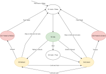
There are many different ways to approach sequential programming tasks and state/transition is a very popular method. This method generally avoids the use of Latch and Unlatch (Set/Reset) instructions and this generally leads to more resilient code.

I've attached what is called a bubble diagram depicting your sequence: It's a bit like a flow diagram; each STATE is represented by a bubble and each transition is represented by an arrow between states. Drawing it in diagram form is a great way to design software before your fingers ht the keyboard.

There are some general rules to state sequences: 1) A sequence is only ever in one state at a time. 2) Each state should exist for a minimum of one entire program cycle to allow interraction with other state sequences. A state sequence can be programmed in ladder logic and requires the use of persistent storage for the state numbers and integer compares.

In the attached example: If state = 4 then Extend, If state = 5 then retract, If state > 2 AND < 30 then Lamp (this puts the lamp on for manual moves)

Maybe someone would fance actually coding this to see how it translates to actual ladder code.

Nick

32487-Page-9.png
 
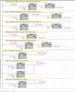
Yes Mang,emender is correct, this is the way I would normally program, some PLC's have state transitions, however, these sometimes are a little hard to use until you get used to them, here is a state system using a variable with values, it is simple so not included are alarm handling i.e. if the sequence does not reach it's destination (Sensor). Note the use of steps of 10, good idea to skip some each transition as it makes adding extra steps easy without having to move things about. Also, if an HMI is in use, by using the SEQ. variable it is often easy to add text driven by the Seq. number so it shows the current operation.
One other thing, it is easy to use a seperate program block in simulation so instead of using real I/O use internal bits, that way you can automate the sensors i.e. if you tell a solenoid to extend then start a timer, then set the sensor bit, reset it when the solenoid retracts, so what you are doing is simulating the actual solenoid moving & triggering the sensors.

Solenoid control.png
 
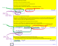
Building on @parky's first example, the point is that this application is most simply, clearly, and concisely coded using two Start/Stop Circuit patterns (cf. here), which is one of several patterns (cf. here) that you will use again and again in PLC programming.

The first Start/Stop Circuit pattern sets the System state

  • System state may be changed to Run by pressing the Start pushbutton
  • System state is maintained in Run by the Seal-in, which is the "remembered*" Run State from the previous scan cycle
    • This is what keeps it running after the Start pushbutton is released
  • System state is forced to Stop by the Stop pushbutton on the current scan cycle.
    • The Start/Stop Circuit pattern is stop-dominant i.e. if both Start and Stop pushbuttons are pressed, the System will be put into the Stop state.
      • Refer to the State Coil/Fault Coil pattern (cf. here) for similar logic that is start-/trigger-dominant.
* It is common to think about the two System Run bit (RUN_LAMP below) operands, in the seal-in branch on the left and in the coil output on the right, as the same bit, as they do both refer to the same bit in memory, but it is important to be aware that those two operands do not refer to the same value. The Seal-in contact examines the System Run bit value from the previous scan cycle, and the output coil writes the System Run bit value on the current scan cycle. The point here is that PLC programming is primarily about time, and the scan cycle is the clock: when something is happening is more important than what is happening; when one fully groks the scan cycle of the PLC, programming becomes much easier.

Anyway, below is my example. Since this is a binary-state system (cylinder is moving either forward or backward when the system is running), it can be easily understood with boolean logic, but as @parky and @Manglemender note, a more complex system would be better served with a sequence of states.

The annotations attempt to make the point that, even if the Start and Stop conditions are complex, i.e each comprises multiple contacts, it still follows the basic pattern (start OR seal-in) AND (NOT stop) => RUN.
Sidebar: for a free and simple emulated system, you cannot beat RSLogix Micro Starter Lite (hobbled version of RSLogix 500) and RSEmulate 500; see here. If you trust eBay, you can often get a used MicroLogix 1100 PLC for under 200USD, which can be programmed with Lite.
Untitled.png
 
For grins, giggles, and code golf, all of the logic could be placed on one rung, see below. One can still recognize the System Start/Stop Circuit pattern, which cascading its System Run output state to both

  • the Forward Solenoid Start/Stop Circuit pattern,and
  • the Reverse Solenoid as not-Forward
constructs, which saves all of two instructions.

Although this is possible, one would not code it this way in an actual application, because it is harder to read, and an important aspect of PLC code is that it be as easy as possible to understand, because that minimizes downtime cf. here.
Untitled.png
 
Actually, will not save two contacts as the branches are effectively instructions, lol.
Had this many times Siemens, Mitsubishi etc. hidden there are the branch instructions not displayed in ladder.
 
Note to OP:


What I learned to do, and still do when writing programs, is create a list of each item or condition that needs to do something.


The list is fluid as when something is done and marked off 3 new things are added. I resorted to using a spreadsheet with 3 sheets - ToDo, Done & MaybeDo (for options not part of the planned project) (I frequently add things for ideas I thought of that could probably be added later so half that work is already done)


Concentrate on one line of the notes to see how that is added to the current program. When the list is fully marked off it's time to debug and think of what you missed.
 
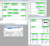
Another approach. Using a construct something like a flip-flop (XOR), but because the second bit is not the same, it is more like a cross between the Start/Stop and State/Fault patterns. This could all be put on one rung again to save two visible instructions, but it is more clear like this.

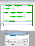
First image has the system off at the reverse limit switch; second image is immediately after that after pressing the start pushbutton, showing that the cylinder goes forward.
cyl_off_rev_limit.png

cyl_just_on_rev_limit.png
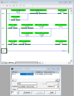
The third image has the system off at the forward limit switch; fourth image is immediately after that and after pressing the start pushbutton, showing that the cylinder goes in reverse.
cyl_off_fwd_limit.png cyl_just_on_fwd_limit.png
The final image shows two cases with the system on between the limit switches, moving forward on the left, and moving reverse on the right.
cyl_on_between_limits.png
 

Similar Topics

I have a SC9-LS24-3 surge protection solenoid cable from automation direct...
Replies
9
Views
1,356
Hi Experts! I'm trying to control a solenoid valve (don't have part number, but I've been told its a 24V DC 30 watt coil) with a PLC output card...
Replies
15
Views
6,612
Hi All, Solenoid bank controls air to 8 cylinders. We used to able to move cylinder up and down by hand no problem but now there is a small amount...
Replies
5
Views
2,433
We have a new system here at our facility that is using Mechanical Relays to control 24 VDC solenoid valves in a hydraulic system. Our relays are...
Replies
13
Views
4,224
Hello, I am trying to make an Automatic Coolant Dispensing station for my client. This unit will be stationed next to a CNC Machine to monitor...
Replies
56
Views
14,534
Back
Top Bottom