Increment subroutine?

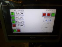
I assume on the HMI then you have bit fields like:
So if Bend 1 & Bend 2 is selected
Bend 1 [0/1] "1"
Bend 2 [0/1] "1"
Bend 3 [0/1] "0"
Bend 4 [0/1] "0"
Then pressing the forward button it will go to position 1 & do the bend.
Operator presses the reverse button it goes back to start position
Operator presses forward button it goes to position 2 & do the bend
Operator presses reverse button goes back to start position.
If pressed again it repeats the selected bend profile, is that correct as above ?
 
Right that makes sense, I will post some logic based on the following:
4 bits to select the 4 bends i.e. either on or off
4 words for the 4 bend values (degrees)
I don't see the forward or reverse buttons, are these hard wired buttons ?
What I would suggest is that you have some tables i.e. x number of 4 bits to use as templates to check that the select bits the operator puts in are valid
For example table 1 is 1-2, table 2 is 1-2-3, table 3 is 1-2-3-4 Table 3 is 2-3 table 4 is 3-4 table Table 5 xxx so a table for each possible combination then you can compare them & generate an alarm if a wrong combination is entered.
Actually, not sure about your PLC but on some bits are not retentive so loose the data when powered down, you could use bytes or words as most PLC's have retentive data areas and easier to do a check by using compares.
Also, use a word for the step sequence, so for example, when you press the fwd button, and the sequence is idle i.e. sequence word = 0
it puts a 10 into it, use a compare to jump to a subroutine that does the check if data valid, if valid then it steps onto 20 (reason for doing it in steps of 10 is it gives you spares for any steps you might want in between, better than having to move steps up one).
 
I see you have a hand-auto switch, but it sound like this is always a more or less manual operation ie the operator pushes forward, then reverse. So the automated part is the angle to bend on each press of forward, and when to cycle back to the first bend.

So does the operator have to position the part before each press of forward?

And do they then have to do something else before pressing reverse?
 
Hand/Auto

The Hand/Auto switch is used to cause continuous motion. Manual you have to hold the button to travel to the set-point. In auto a momentary touch moves it the set-point. Forward (bend) and Reverse (return) are always separate functions.
 
So it sounds like all of the subroutines are basically the same steps:
1) wait for operator to press [forward]
2) e extend cylinder to bend angle, which bend angle is specific to that subroutine
3) wait for operator to press [reverse]
4) retract cylinder to a bend angle of 0

So the only difference between subroutines is the bend angle?
 
That's good to know, I had a quick look at kinco, it it is IEC compliant, but it appears to be a bit limited, may depend on type.
Tomorrow I will get something on my simulator in ladder (I noticed that some of the functions are depicted as like in IEC for example the Compare etc.).
One thing came to mind, if the bend functions are identical appart from the setpoints for position you could use one function block & pass that information to the calls to them i.e. instead of creating 4 blocks one for each bend, you create one, call it multiple times with parameters passed to it.
It makes sense to create another function/subroutine for the return, this could be just one block called after each call to the bend routines, it does not need different parameters as it only needs the zero to get back (well I assume).
 
Dr bit:


All subroutines are the same except for set-point (bend angle) and there output bits one for forward bend one for reverse bend (at zero).
 
Last edited:
Dr bit:


All subroutines ate the same except for set-point (bend angle) and there output bits one for forward bend one for reverse bend (at zero).


So the automation is something like:
1)wait for a press of forward button
2) once that press of the forward button is detected, turn on forward bend output bit, which starts the hydraulic cylinder moving
3) when encoder indicates table angle has reached the setpoint angle, then turn off forward bend output bit

There is similar logic to return to an encoder-measured angle of zero in response to a reverse button press

Am I close?
 
Does the reverse output bit actually bend the material, or does it only return the table to an angle of zero, so the part can be either repositioned for the next forward bend, or removed from the table?
 
You can still use a function block, just use internal bit memory for the outputs then or them for the drive
If Sequence = 10 Call FB_Move_Fwd
IN = Bend_1_Radius
OUT = Bend_1_Drive_Fwd
If Sequence = 20 Call FB_Move_Rev
OUT = Move_Back_1

If Sequence = 30 Call FB_Move_Fwd
Call FB_Move_Fwd
IN = Bend_2_Radius
OUT = Bend_2_Drive_Fwd

If Sequence = 40 Call FB_Move_Rev
OUT = Move_Back_2


If Sequence = 50 Call FB_Move_Fwd
Call FB_Move_Fwd
IN = Bend_3_Radius
OUT = Bend_3_Drive_Fwd

If Sequence = 60 Call FB_Move_Rev
OUT = Move_Back_3

If Sequence = 70 Call FB_Move_Fwd
Call FB_Move_Fwd
IN = Bend_4_Radius
OUT = Bend_4_Drive_Fwd

If Sequence = 80 Call FB_Move_Rev
OUT = Move_Back_4
Bend_1_Drive_Fwd
-----| |-----------------( ) Drive Fwd
Bend_2_Drive_Fwd |
-----| |--------------+
Bend_3_Drive_Fwd |
-----| |--------------+
Bend_4_Drive_Fwd |
-----| |--------------+

Do the same for reverse or just or the seq numbers & call the reverse function once

EDIT: Actually, there would be intermediate steps for each one I forgot that the operator presses the buttons to do each operation so perhaps
Seq = 5 wait foroperator to press button, set to 10
& so on between each operation see what I mean about leaving spares lol

This would be a lot easier if kinco could use multi dimensional arrays but it can't only single ones
 
Last edited:
Logic is posted in post #8 as PDF.


Yes, but (A) the comments in same are less than illuminating, and (B) from Post #1 it appears that Pos1/Pos2/Pos3/Pos4/... are the "enable bits (set by the HMI?)" and the problem is how to control booleans Pos1/Pos2/Pos3/Pos4 to execute 1-then-2, 1-then-2-then-3, or 1-then-2-then-3-then-4, not 1-AND-2-simultaneously, 1-AND-2-AND-3-simultaneously, 1-AND-2-AND-3-AND-simultaneously, and possibly repeating that cycle, as only one of those booleans should be 1 at any given time. So you need additional data tags for each subroutine.

Logic to solve (B) is posted in post #4.
 
Last edited:

Similar Topics

Hi, Am I being daft (again)? I want to increment a tag (Integer) by 1 each time a button on the HMI is pressed. Before the button press, the...
Replies
22
Views
2,363
Hi, I have a stand alone inspection unit with no PLC but I can send 24v input signals to the machine PLC to show a good read and a bad read when...
Replies
9
Views
779
The attached pdf shows a CPT instruction that should calculate the value of tag Cell_Charge_Percent_Remaining[1]. I've included the relevant...
Replies
4
Views
1,528
I have a considerable amount of modbus register data tags from a plc already setup in crimson. I have them setup in alphabetical order with...
Replies
4
Views
2,095
I am using the Library Designer tool to create PLC code. One of the standard routines that our company uses for simulation has individual XICs...
Replies
0
Views
1,513
Back
Top Bottom