Increment subroutine?

Also, since, per main.pdf, subroutine Position1 is only called if boolean Pos1 is 1, then why are there redundant (i.e. unnecessary) Normally Open contacts testing Pos1 in subroutine Position1?


Same query for boolean SYSenb?


Also, what do B01 and Z01 do?
 
Last edited:
Logic is posted in post #8 as PDF.

Are you saying that this code works?

Forget about B01 and Z01; I understand them now.

Where is the logic that assigns the values of the tags Extend and Retract? [Never mind, I figured them out: they are the Forward and Reverse buttons, respectively]
_
 
Last edited:
I see another problem, he is using subroutines to drive the bends, the enable logic that runs those routines means when it reaches position it moves onto the next subroutine, this means that the drive could still be on as it is not processing the routine, need to ensure the bit is reset before exiting the routine.
 
I see another problem, he is using subroutines to drive the bends, the enable logic that runs those routines means when it reaches position it moves onto the next subroutine, this means that the drive could still be on as it is not processing the routine, need to ensure the bit is reset before exiting the routine.


Yes, I think this is the genesis of the original post:

  • The Pos1/Pos2/Pos3/Pos4 booleans' values are assigned by the HMI to indicate which bends are enabled,
  • So the way the code is written now, it is executing all of the enabled bend subroutines on each scan, even though only one bend should be executed on any one scan.
I am pretty sure those PosX booleans are meant to be static, at least from the viewpoint of the program, so they can only be changed from the HMI.

What is missing is separate per-bend variable(s) to keep track of which bend is active during any one scan.
 
Those subroutines have an ENO output just use that to control the outputs, once the sub is not called, it will turn off the output.
 
Those subroutines have an ENO output just use that to control the outputs, once the sub is not called, it will turn off the output.


That won't solve the basic problem, which is that the way it is coded now it will call all four bend subroutines on each scan, when it should be calling the first subroutine that has not yet completed. That is the problem that needs to be solved.
 
Here you go. This code will execute from one to four bends in order, using the Forward and Reverse input buttons to initiate the extend and retract for each bend, and rolls over to to restart at Bend 1 when the last enabled bend is complete.

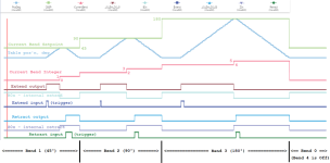
The four separate bend subroutines have been discarded and replaced by a single bend routine that gets it setpoint angle based on a Current Bend Integer/ That integer runs from 0 to 7, with two values assigned to each bend: even for extend; odd for retract. trailing bends that are disabled cause the Current Bend Integer to increment by 1 per scan, while leaving the cylinder at its Home position, until the integer reaches 8, at which point it rolls over to 0, ready to restart with Bend 1.


The HMI interface is slightly different as I prefer the more reliable Set-And-Forget design pattern when the HMI is writing PLC values.

Each of the four calls to Function Block Setpoint_and_CBact on Rung 2 in the RunBends program could be replaced with a single rung (GE; [branch]; MOV; [next branch]; -]/[-; -(R)-) in RungBends, to make it easier to see what is going on.
 
Last edited:
DR beat me to it, have you utilised the FWD/REV buttons on each cycle.
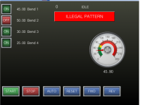
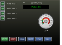
Here is one that uses sequence steps with FWD/REV, auto/man (No manual drive added), reset to home, illegal pattern disable, display current sequence.
no subroutines not needed

HMI2.png HMI1.png
 

Attachments

  • Bender1.pdf
    115.1 KB · Views: 5
...Here is one...


Nice!

OP should definitely drop the separate subroutines.

I used Function Blocks to encapsulate repeated logic and unclutter the main routines. I am pretty much using OP's code, but within a slightly different framework.

If I removed those function blocks and expanded their code into the main routines, it would be about the same number of rungs as @parky's version.
 
Yeah, not much point in using subs or FB's on such a small bit of code.
I suppose you could get rid of the enable buttons & have a drop down list of combinations just leave the bend settings, or even better recipes for standard profiles.
I thought about doing the same with bools instead of a seq word but then you loose the neat way of using a text list to show the current operation.
 
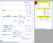
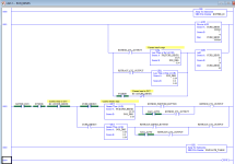
The [Document Generator] for CCW makes such ugly outputs, so attached is a PDF of the RunBends program of the multi-bend application. It still suffers from inherent CCW ugliness, but it fits on one page and is at least easier to read.

Also expanded are the four function block calls that (i) assign the global setpoint for the current bend, and (ii) reset the current bend active boolean, into four rungs, so the essential logic to answer the original post is here:

  • Rung 1
    • Make [Current Bend Integer] roll over from 7 to 0 to ensure system resets to be ready for [Bend 1 extend] state after Bend 4 completes
    • Assume current bend is active
  • Rungs 2-5
    • Use setpoints for each bend up to current bend to overwrite the global current bend setpoint, which means the final value of the global setpoint on the current scan will be that of the current bend
    • Reset the current bend as inactive apropo the HMI inputs
  • Rung 6
    • Single all-bend-capable rung equivalent to all of OP's Position subroutines.
  • Rung 7
    • Increment [Current Bend Integer] at end of active current bend's extend and retract events; also increment for any inactive current bends
      • Values (sequence steps) of [Current Bend Integer]
        • 0 - Bend 1 extend (B0x = 1; CBSP = SP1)
        • 1 - Bend 1 retract (Z0x = 1)
        • 2 - Bend 2 extend (B0x = 1; CBSP = SP2)
        • 3 - Bend 2 retract (Z0x = 1)
        • 4 - Bend 3 extend (B0x = 1; CBSP = SP3)
        • 5 - Bend 3 retract (Z0x = 1)
        • 6 - Bend 4 extend (B0x = 1; CBSP = SP4)
        • 7 - Bend 4 retract (Z0x = 1)
        • 8 - Final retract complete; integer will roll over to 0 on next execution of Rung 1
 
Here is a much nicer-looking version coded for the MicroLogix platform. It's nothing fancy: the falling edges implemented here with multiple atomic contacts would be cleaner with the self-contained edge detection instructions available on the Kinco.

But with indirect addressing (i.e. indexed arrays), it takes but a half a dozen lines or so to implement the whole megillah.

bend_table.png
 

Attachments

  • bend_table.pdf
    274.6 KB · Views: 7
I can name that tune in "two" rungs (well, more like three or four depending how I count branches ;)) and two dozen instructions.

bend_table_2rungs.png
 

Attachments

  • bend_table_2rungs.pdf
    272.8 KB · Views: 4

Similar Topics

Hi, Am I being daft (again)? I want to increment a tag (Integer) by 1 each time a button on the HMI is pressed. Before the button press, the...
Replies
22
Views
2,367
Hi, I have a stand alone inspection unit with no PLC but I can send 24v input signals to the machine PLC to show a good read and a bad read when...
Replies
9
Views
779
The attached pdf shows a CPT instruction that should calculate the value of tag Cell_Charge_Percent_Remaining[1]. I've included the relevant...
Replies
4
Views
1,529
I have a considerable amount of modbus register data tags from a plc already setup in crimson. I have them setup in alphabetical order with...
Replies
4
Views
2,095
I am using the Library Designer tool to create PLC code. One of the standard routines that our company uses for simulation has individual XICs...
Replies
0
Views
1,513
Back
Top Bottom