Issue with modbus communication between MLX 1400 and jumo controller

rejoe.koshy

Member
Join Date
Dec 2011
Location
kolkata
Posts
195
Hey Guys,
I am struggling to read data from a "JUMO" make controller using modbus RTU with MLX1400. The communication between the devices has been established but the data received is not in line with the actual values displayed on the temperature controller (JUMO).I am assuming its got something to do with the address (registers) of these values .I am trying to read the process value and set point.

Can anyone who has worked with the controller help?
 
1) Can you give an example of what are the values you are reading via Modbus, and what you think they should be?
2)try changing the address that is being read by 1.
 
1) Can you give an example of what are the values you are reading via Modbus, and what you think they should be?
2)try changing the address that is being read by 1.

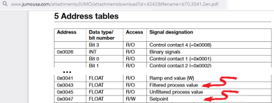
The manual of the controller states the address for process value is 0043 (hex). So when I am using the same in MLX1400, I converted the hex value to decimal (which would be 67) and put that in the MSG instruction. Two words are read in to two integer address , which I am converting to a float (F8) value using CWP instruction.
Now its giving me abrupt values like -1.00056 e^-17 as opposed to real temperature values.


P.S I am using a d-tron model controller.

Where could I be going wrong?
 
Use logic to capture the raw integer values before they are converted to floating point value with the CPW instruction.

When you see a tiny or huge floating point value as the result of that sort of conversion, the problem is almost always byte order.
 
Use logic to capture the raw integer values before they are converted to floating point value with the CPW instruction.

When you see a tiny or huge floating point value as the result of that sort of conversion, the problem is almost always byte order.


I somehow got it work!. You were bang on about the byte order , which was the issue.

The only thing bothers me is the address of the registers which I am reading is so different to what is mentioned in the operating manual.In fact, the set points have become process values and vice -versa.

Anyways , so long as it works , good to go!!

Thanks lot ..@Ken @drbitboy
 
The only thing bothers me is the address of the registers which I am reading is so different to what is mentioned in the operating manual.In fact, the set points have become process values and vice -versa.


Are the setpoints and process values in alternating registers?


Then this may be the off-by-one problem: could location 0 in the JUMO controller be Register 40001 in the Modbus protocol?
 
Are the setpoints and process values in alternating registers?


Then this may be the off-by-one problem: could location 0 in the JUMO controller be Register 40001 in the Modbus protocol?

OP: 0043 - filtered process value, 0045 - unfiltered process value, 0047 - set point.

Actual : 0047 - filtered process value, 0043 - set point
 
OP: 0043 - filtered process value, 0045 - unfiltered process value, 0047 - set point.

Actual : 0047 - filtered process value, 0043 - set point


Oh dear, that's an error in the manual then.


Btw, for the record, before the CPW into each float, do you have to

  • swap the 16-bit words from Modbus (e.g. registers 43 and 44 for setpoint)
  • or swap the bytes in the 16-bit (two-byte) words,
  • or both?
Thanks!
 
Oh dear, that's an error in the manual then.


Btw, for the record, before the CPW into each float, do you have to

  • swap the 16-bit words from Modbus (e.g. registers 43 and 44 for setpoint)
  • or swap the bytes in the 16-bit (two-byte) words,
  • or both?
Thanks!

You need to swap the 16 bit words from Modbus and use CPW to convert it to a float value
 
You need to swap the 16 bit words from Modbus and use CPW to convert it to a float value

That is odd, because the manual has the Jumo word and byte arrangement in the Modbus stream in the same order as it is in MicroLogix (see images below). I wonder if that is another error in the manual.

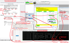
OP: Could you please post a screenshot of your MicroLogix code, also showing what the data words look like

  • as they arrive on the MicroLogix from Modbus,
  • after they are switched in MicroLogix,
  • and the final floating point result?


xxx.png => yyy.png
 
The plot thickens

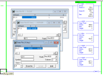
See images below.

The first image demonstrates that using 68 as the [MB Data address] entry in the MSG Setup Screen results in 67 being placed both


  • In the .TFN (Target File Number) element of the MG structure, and
  • In the data message itself.
And vice versa: writing a 67 into .TFN results in a 68 in the Setup Screen.

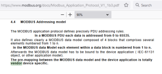
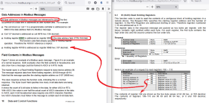
The second and third images show relevant sections of Modbus protocol documents from www.modbus.org: the point I am getting at is that there is

  • a one-based data model, and
  • a zero-based model for the bits in the Protocol Data Unit (PDU)
    • i.e. a zero-based model for the bits in the actual messages sent from client to server.
P.S. I love that use of "totally" in that document.


xxx.png

zzz.png

yyy.png
 
So when OP wrote this:


The manual of the controller states the address for process value is 0043 (hex). So when I am using the same in MLX1400, I converted the hex value to decimal (which would be 67) and put that in the MSG instruction.

[...]

Where could I be going wrong?

The answer to the question is, where did they put the 0x0043 (67 decimal) value? Did they enter it into the MG structure's .TFN element, or did they enter 0x43 into the MSG instruction's Setup Screen? Because if it's the former, then as sure rain and sunshine are in a green blade of grass, 0x42 was sent in the PDU to the Jumo controller, which means, if the Jumo addressing (cf. image below) is zero-based, then OP is picking up the high (16-bit) word of the [Ramp end value (W)] floating-point value from 0x0042 and the low word of the [Filtered process value]* from 0x0043. Similarly, if 0x0047 (71 decimal) was used in the Setup Screen for the Setpoint*, then they would get the high word of the [Unfiltered process value] from 0x0046 and the low word of the [Setpoint]* from 0x0047. Which explains why OP had to swap the words to reconstruct the double-word floating point values, which only works because the setpoint and process values are likely of the same order of magnitude, so the sign (1 bit), exponent (8 bits) and upper 7 bits of the mantissa in the high word are similar, for a process in control.

This is all speculation, of course, but what I suggest as a way to resolve all of this is to get all of the data of interest (0x0043 and 0x0047) plus a pad of data around it e.g. put 0x0040 (64 decimal) in the Setup Screen and get 16 elements, so the PLC will have registers 0x0040-0x004f, or perhaps 0x003f-0x004e or 0x0041-0x0050, and they can be inspected to see what makes sense.

* N.B. OP said it looks like the [Setpoint] and [Filtered process value] registers in the physical controller are swapped with respect to where they are supposed to be per the manual.


xxx.png
 
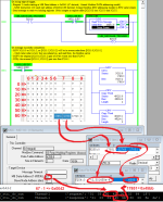
The image below shows how to get a 32-bit floating-point value of 3000.0 from a Modbus server at PDU model address 0x003f; note that

  1. The 16-bit words do not need to be switched if
    1. the low 16-bits of the floating-point value are at PDU model address 0x003f, and
    2. the high 16-bits are at PDU model address 0x0040, because the MicroLogix 1100 byte order is already LSByte-first.
  2. The 1-base [MB Data (Model) Address (1-65536)] is 64 (0x0040) = one more than the PDU model address 63 (0x003f)
xxx.png


[Update: fixed typos in addresses)
 
Last edited:
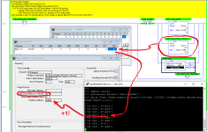
The image below demonstrates what I think OP may be doing:

  • The [32768,17723] pair of 16-bit integer words in PDU model addresses 67 and 68 are the desired source of the words to be COPied to the floating point value pf 3000.0 (see previous post)
  • However, because OP put 67 as the [MB DATA (model) address] in the MSG Setup Screen, they are actually getting the [17851,32768] pair of words in PDU model addresses 66 and 67,
    • Which pair of words they need to switch to get a reasonable floating point value,
    • And because they are pairing the 17851 at 66 from the previous floating-point value, instead of the 17723 at 68 from the target floating-point value, with the -32768 at 67, they end up with a value of 6000.0 instead of the desired 3000.0.
xxx.png
 
Last edited:

Similar Topics

Hey everyone, I am seeking assistance on finding and solving potential cause of a Modbus RTU issue, from a Micro820 PLC. We are unable to...
Replies
6
Views
1,308
I have had to write my own Modbus ASCII "driver" for an old DL05 talking to a GS4. I am using the Modbus Slave program for testing. A PID is...
Replies
17
Views
6,991
Hi All, I have a question would like to ask the experts: my system has two Rx7i PLCs and I'm having them communicate with an RTU (D25) via modbus...
Replies
2
Views
2,066
Hi folks, I'm running eCockpit version 1.3.1.4 I have set up a Modbus client function using the standard library module: FbMbMasterTcp. My...
Replies
4
Views
3,842
Hi there, I'm using an S7-1200 system and I have followed a Siemens application example to read/write data to 1x slave using Modbus RTU and a...
Replies
2
Views
4,181
Back
Top Bottom