Issue with modbus communication between MLX 1400 and jumo controller

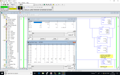
Please find the attached images of the code that I am using. I wasn't very happy with the value of set point I was getting because when the value was set to zero on the controller, the value read in to PLC was an abrupt number 1.6732 e^-16.

Hence I decided to read values from 0045 for PV and 0049 for SV., which means the addresses have been offset by one.

XXX.png YYY.png
 
I wasn't very happy with the value of set point I was getting because when the value was set to zero on the controller, the value read in to PLC was an abrupt number 1.6732 e^-16

Hence I decided to read values from 0045 for PV and 0049 for SV., which means the addresses have been offset by one.

Yes, that is the point of my recent posts, which predict that exact result. It also means the code should not need to to switch the 16-bit words.

However, as long as there are odd (non-even) values for the [MB Data Address (1-65536)] field in the MSG/MG Setup Screen, I fear the MicroLogix code is still mixing 16-bit words from different FLOAT registers of the Jumo device.

Perhaps a more useful approach would be to Read 16 (or more) consecutive 16-bit words from the Jumo, e.g.

  • use 64 (decimal; 0x0040) for the [MB Data Address (1-65536)] in the Setup Screen, and
  • use 16 for the [Size in elements] field in the Setup Screen,
for a single MSG/MG instruction, then we can look at the resulting sixteen 16-bit words (MB Data Model addresses 64-79 decimal; MB PDU Model addresses/Jumo registers 0x003f-0x004e), data in the N-file (e.g. N7:240 - N7:255), and if there is a zero value between two non-zero float values, we can determine its exact location.
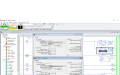
 
OP: use 0.003921509 as the manually-entered Setpoint instead of 0, and [(03) Read holding registers] at least six registers, from a few registers before to a few registers after the Setpoint's Modbus address.

The unique resulting pair of values (-32768 and 15232 = 0x8000 and 0x3b80) in the MicroLogix target integer data file (e.g. N7:...) will enable determining the exact location, and register order, of the 32-bit floating-point Setpoint's two 16-bit integer holding registers.

There could be some roundoff, but that would only change the -32768 to somewhere in the range of [+32765:-32766] => [0x7FFD:0x8002]; the 15232 (0x3b80) will be there.

xxx.png
 

Similar Topics

Hey everyone, I am seeking assistance on finding and solving potential cause of a Modbus RTU issue, from a Micro820 PLC. We are unable to...
Replies
6
Views
1,307
I have had to write my own Modbus ASCII "driver" for an old DL05 talking to a GS4. I am using the Modbus Slave program for testing. A PID is...
Replies
17
Views
6,983
Hi All, I have a question would like to ask the experts: my system has two Rx7i PLCs and I'm having them communicate with an RTU (D25) via modbus...
Replies
2
Views
2,064
Hi folks, I'm running eCockpit version 1.3.1.4 I have set up a Modbus client function using the standard library module: FbMbMasterTcp. My...
Replies
4
Views
3,842
Hi there, I'm using an S7-1200 system and I have followed a Siemens application example to read/write data to 1x slave using Modbus RTU and a...
Replies
2
Views
4,181
Back
Top Bottom