L.E.D. AC Power Adapter Help

g_4key

Member
Join Date
Aug 2014
Location
SC
Posts
42
Hey everyone!

Looking for some help on a power supply I'm trying to "mod". I have a old HP AC power adapter for 100-240VAC input @ 1A with a output of 32VDC @ 720mA or 16VDC @ 610mA. What I'm needing help with is that I need this to power 8 L.E.D's requiring 24VDC @ 11mA each. I was thinking of putting a resistor in the the 32V line to drop it down to 24VDC. Is there a better was of going about this? Please note that I'm doing this because I'm trying to build a project from scrap electronics and parts that are no longer being used anymore. I do have a limited but nice variety of capacitors and resistors. If necessary or not possible to achieve my goal, I suppose I can break down and buy some components or a power supply outright. Any advice would be much appreciated and thanks in advance for your time.
 
Last edited:
...I'm trying to build a project from scrap electronics and parts that are no longer being used anymore.
The best would be to find a used 24 VDC power supply. Those are not as plentiful, but they do exist. But if all you can find is the 32 VDC, then a large-wattage resistor can be used, but make sure it has a high-enough wattage rating so that it does not get so hot that it burns and causes a fire.
 
I'll probably end up buying a power supply for hobby reasons in the future, but for now I'll just use a resistor. Based on some quick math if I'm not mistaken all I will need is a 5 watt resistor. Here is how i got that 24VDC x .011A got .264 Watts @ 10 L.E.D.'s which gave me 2.64 Watts. All i have is 2, 5 and 10 Watt resistors.
 
I'll probably end up buying a power supply for hobby reasons in the future, but for now I'll just use a resistor.
You would need 2 resistors to build a Voltage Divider circuit. If you used a R1 10-watt 20 ohm resistor in series with a R2 10-watt 10kOhm (10000 Ohm) resistor, then wired your 8 LEDs in parallell with the R2 10K resistor, you would get about 31.9 volts across R2 no-load, and about 17.4 volts with all 8 LEDs ON.
 
+---------------+
| |
| < R1 = 20 Ohms
| > 10 watt rated
| |
|23 watts max |
(32v) +-------------+
| | |
| < R2 = 10k |
| > 10 watt o 8 Leds, 24 V at 88 mA
| | rated o = 23.9 Ohms
| | |
+---------------+-------------+

 
How does the power supply change from 32V to 16V? Pry it open. You could probably modify it to produce 24 Volts.
If LED's are rated for 24 Volts, then they have a regulator (or just a resistor) built-in. LED's are 2 volts, and need controlled current, not controlled voltage.
There isn't nearly enough information on the parts you are using to give a proper answer.

tumblr_mry1ktfEWI1qk3jflo1_250.jpg


AC Power Adapter Info
http://www.pluginreplacements.com/products/hp-genuine-0957-2084-ac-adapter-power-supply-cord-5940xi-5440xi-oem-5940-5440-xi

http://www.amazon.com/HP-0957-2084-Adapter-Discontinued-Manufacturer/dp/B0022MU5J0

L.E.D. Info
AP6M222
https://www.idec.com/language/english_j/ControlUnits_Switches/EP1176_AP_UP6_7_8_9_10_12_16mm/AP_8_10_12_16_Section_EP1176-0.pdf
 
One resistor for each LED (If you will be switching individual LEDs on and off then use this) ...

8 volt drop at 11ma = 727.27 ohms at .088 watts


If you want to do only 1 resistor decide how many LEDs, 8 or 10. (If all LEDs will be switched on/off at the same time then this may be ok)

8 / (.011 * number of LEDs) = Ohms
8 * (.011 * number of LEDs) = Watts

Due to minor differences in LEDs may get brightness variations.
 
Last edited:
I could get this at my local radio shack, would I need anything else like a Potentiometer, etc?
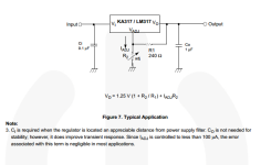
The schematic on pg. 5 shows that R2 is a potentiometer (or rheostat if you use just two leads of a potentiometer). My calculation is a 5k adjustable pot. I don't know your experience in reading a schematic or building, but, all the parts are shown in the schematic drawing on pg. 5 of the pdf in the link. All capacitors should be rated at 35 volts DC or higher. C0 is 1 microfarad (uf) C1 is .1 microfarad (uf). R1 is a 240 ohm resistor (get the nearest standard value). I'm guessing but probably 1/2 watt rating will be good enough for both R1 and R2 (the pot).

Edit:
BTW, I think Bernie's solution (post #11) is the simplest and cheapest.
 
Last edited:
I could get this at my local radio shack, would I need anything else like a Potentiometer, etc?

Since you specify that it is a 24 volt string, I'm wondering if it doesn't have a current regulator already built in. It might run on 36 volts as is. Something to look into anyway.

The app example is pretty simple and dirt cheap. Based on what you've already have, you could eliminate the caps and just use a 3.9k (in lieu of the pot for R2), and a 220 ohm resistor (rather than the 240 ohm specified for R1). I chose the 220 and 3.9k ohm resistors so you would be able to use standard resistor sizes.

Doing the math (which is always risky for me), I come up with 23.4 volts

1.25 * (1 + 3900/220).

The "boost" that you should get from Iadj*R2 should be about .39 volts. Which will put you very, very close to 24 volts.

So, you will need a LM317, a 220 ohm resistor and a 3.9k ohm resistor from the Shack. Wire it up "Dead Bug" style and you should be good to go.

LM317_App_Ex.png
 
I'm going to expand on Bernie's post, since he hit it right on the nail.

It's not likely to have a regulator in it. More likely it's just a resistor in series with the LED. For a 24VDC circuit, assuming a 2V drop across the LED, that leaves 22V to be taken up by the resistor. The sheet says 11mA draw. 22V/11mA=2000ohms. Okay, well enough. But, with a 32V Power supply, you have 8 more volts to worry about. Our total resistance needed would be 30V/10mA=3000ohms. With the 2000 ohms already in the circuit, that leaves 1000 ohms. You could likely put anything in between 680 and 1.2K and still work. Personally, I'd go for 820ohms.

That being said, even putting it straight to 32V, I calculate the draw at 15mA, which the LED should be able to handle. for safety's sake though, add a series resistor to each one.

2014-10-28_8-03-45.png
 
Last edited:
Reply to Everyone

I will be buying that 24v supply from automation direct to avoid this in the future but it’ll provide some experience I suppose. In respect to this “Make R1 10 Ohm, 10 Watt. Don't see a need for R2.” keithkyll, is that for what Lancie1 posted? bernie_carlton, these lights I plan on hooking up to a P.L.C. to run a traffic light simulation with an input simulator card for a G.E.-Fanuc 90-30. The output card is a DC 12/24V 8-outputs NEG/Negative Logic. So red will be on for 30 seconds then Green 25, Yellow 5 and a slight delay where both Red lights will be on for 2-5 seconds. I will also be implanting a subroutine where orange lights will flash alternately when an input switch is flipped on for an emergency light. So I think what you said about 8 volt drop at 11ma = 727.27 ohms at .088 watts maybe more appropriate if I’m thinking right correct me if I’m wrong. Rootboy that’s sounds very simple and easy but I’m not sure what you mean by dead bug could you please expand pardon any ignorance. JordanCClark you’re right there is no voltage regulator only an, ”built-in protection diode ensures a reverse withstand voltage of 100V”. With the provided schematic I only have one question is R1 an internal resistor in that L.E.D. or one I would solder/wire in with it?
 

Similar Topics

Hi Guys, I am just trying some PLC stuff to learn by myself. I am buying a Siemens S7-1200, DC DC DC (1212C with power input as DC) model. I...
Replies
6
Views
2,280
Hello All, Im pretty confident i fried my ac adapter. It is a 120vac to 24 vdc power relay, sdr-120-24. I had it hooked up to a...
Replies
17
Views
4,032
We have a few profibus networks that have ABB ACH 550 drives using the RPBA-01 profibus adapter for control. The issue we currently have is that...
Replies
1
Views
3,944
Hello all, I am currently trying to program a PowerFlex 525, version 7.0. We had a power outage recently and when the power was restored, the...
Replies
10
Views
195
Looking at installing point io, with a 1734-AENTR communications adapter and ten 1734-IT2L modules. In IAB it installs a 1734-EP24DC after every...
Replies
1
Views
49
Back
Top Bottom