

Hi, I am new to ladder logic. I have completed a code in the Xinje PLC XC3-32RT-E for one of the machines I am developing. Currently the program runs once and stop, and I am struggling to loop the program. I can send you the code and explain about the machine if required. Can y'all please provide an idea on how to proceed ? Thanks in advance.
You are using an out of date browser. It may not display this or other websites correctly.
You should upgrade or use an alternative browser.
You should upgrade or use an alternative browser.
Looping a Program in Xinje PLC
- Thread starter tharinduk
- Start date

Looping can be done in a couple of ways for example a for next loop, or conditional jump I have never programmed this plc but it is almost a copy of the Mitsubishi, the instructions are virtually the same, however, a quick look at the manual does not show the break instruction (used in some Mitsi's to jump out of the loop), so if the loop is variable then you would have to use the CJ (conditional jump) function.
The other thing I could not find was the Indirect address or index registers (Z in Mitsubishi) this allows offset address of variables & can be incremented .
Perhaps post a pdf of the code.
The other thing I could not find was the Indirect address or index registers (Z in Mitsubishi) this allows offset address of variables & can be incremented .
Perhaps post a pdf of the code.
Hi Parky, Thank you very much for your reply. Highly appreciate it.Here is some mitsi code, a quick look at the manual I could not see if the for/next loop has a break function if the loop is variable, also could not see how you indirectly point to variables like mitsi but anyhow attached is some code I use.
I am not saying I was able to make a loop successfully but I was able to somewhat make a loop. But there is another issue now. Before coming to that, I will briefly explain the nature of my project.
This machine is being built to make cuts in garment panels in order to cut them in to 2. Inputs and outputs are as follow;
Inputs:
X0 - Emergency
X1 - Selector Switch
X2 - Home (Proximity) Sensor (to detect the home position of the linear guide)
X3 - Photo Electric Sensor 1 (which detects the presence of the garment)
X4 - Photo Electric Sensor 2 (which detects the presence of the garment)
X5 - Reed Switch (which is set on to the pneumatic cylinder)
Outputs:
Y0 - Motor Pulse
Y1 - Motor Direction
Y2 - Pneumatic Cylinders (which are activated through a solenoid valve)
Y3 - Scissor (which is activated through a relay)
When X0 is released and X1 is switched on, and X3 and X4 garments sensing sensors are triggered, the pneumatic cylinders are actuated and holds the garments against the machine bed. When the pneumatic cylinders are actuated and are fully down, X5 is activated. Thereafter, a 1.5 second delay, the scissor which is mounted on top of the linear guide and the stepper motor is actuated and starts sending the scissor forward up to predetermined pulses value. Once it reaches the end, the scissor stops, the motor comes to its initial position and the cylinders get retracted. This is the basic program I have written.
After that I have tried looping using memory bits and Xinje's built-in STL flow functions. Now it is looped somewhat. Now it takes the scissor forward and backward once; and when the next loop starts, the scissor moves forward successfully but does not come back. All the other functions are working as required but the scissor does not come back as the motor is not actuated in the second loop. I am currently stuck there. I believe this has something to do with resetting the motor direction and the pulses. I am not sure though.
Can you kindly help me on this. I have attached a pdf format and the Xinje PLC program of the same, herewith. Thank you in advance.
Attachments
First of all, some of the instructions for the motor ******* seem to be different in the mitsi for example there is no STOP function.
I do not understand why you are using the STL that in reality is just a flow, I never use them It is not strictly a loop as the program is cyclic so the whole progam loops just jumps or logic determine what segments of ladder are processed. I use an integer variable to run each step for example assume I have a variable called Seq_Number (D20), then create my flowchart
So lets assume I have a sequence as follows:
Seq. 0 = IDLE
Seq. 10 = Start pressed waiting for part
Seq. 20 = Part Detected, clamp Part
Seq. 30 = Clamp Cl,amped step on to move motor
Seq. 40 = Move motor FWD
Seq. 50 = Motor at position, Stop motor
Seq. 60 = Stamp part
Seq. 70 = Return motor
Seq. 80 = Unclamp
Seq. 90 = Unclamped, move 10 into Seq.
Note: I use steps of 10, this means if I need a few extra steps it is easy to add them i.e. insert an extra one at 25 without having to move the following ones about.
As a quick demonstration here is a simple 2 way traffic light system using a sequjence, it just uses timers but a machine would use sensors & timers for it's current state to move onto the next state.
also I suggest you use a little more documentation i.e. symbols for those memory bits & ladder comments it will make it easier to understand by others & if you re-visit in a few years time.
Attachments
drbitboy
Lifetime Supporting Member

Outputs:
...
Y1 - Motor Direction
This says Y1 is the Motor Direction, but in the PDF, the program comments say Y6 is the Motor Direction.
SET and RST instructions are fine, but when they are sprinkled throughout the program like this, it is difficult to understand how all the contacts and coils interact.
from @parky:
Seq. 0 = IDLESeq. 10 = Start pressed waiting for partSeq. 20 = Part Detected, clamp PartSeq. 30 = Clamp Cl,amped step on to move motorSeq. 40 = Move motor FWDSeq. 50 = Motor at position, Stop motorSeq. 60 = Stamp partSeq. 70 = Return motorSeq. 80 = UnclampSeq. 90 = Unclamped, move 10 into Seq.
This would be much easier programmed as @parky suggests: using integer steps:
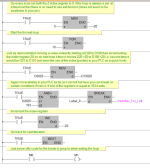
- Each output can be independently controlled on one rung, using only one coil, by the step number value.
- E.g. the clamp cylinders will be extended when the step number value is between 19 and 71, i.e. when the step number is any one of 20, 30, 40, 50, 60, or 70.
- Also, the motor will be running when step number value is either 40 or 70, and off otherwise.
- The transition between steps can be independently controlled, based on the inputs and the current step.
- E.g. When the step number value is 20 (part detected but not clamped yet; cylinders are extending) AND the X5 input bit is 1 (cyclinders are fully extended i.e. the part is clamped), then the step number value is incremented to 30 (Part is clamped, motor run start-delay timer).
- E.g. When the step number is 30, then the motor start-delay timer can run, and when that timer expires (T1 value becomes 1), that can increment the step number to 40, which will reset motor start-delay timer on the next scan cycle (because the step number is not 30).
- E.g. any time either the Emergency input value is not 1 or the Start input value is not 1, then the step number value can be changed to 0 (IDLE step), which will stop everything.
drbitboy
Lifetime Supporting Member
If you still want to do it with bits to keep track of state (step), instead of integer step numbers, then you can use the canonical Step pattern (see here; @OkiePC this is not another AB manual). Because this uses seal-in (latch) logic and unconditional coils, instead of SET/RST instructions, it forces you to put all of the logic for each step on one rung, which makes it easier to read and understand (especially a year from now, as @parky mentioned ") ).
).
Functionally, using an integer number is similar to your SET/RST logic, because writing a value to an integer is similar to SET/RST instructions, but for multiple bits. Also, using bits in this canonical Step pattern is functionally similar to those two methods, because each step's bit is sealed-in (latched), the same as it would be when using SET/RST instructions.
).Functionally, using an integer number is similar to your SET/RST logic, because writing a value to an integer is similar to SET/RST instructions, but for multiple bits. Also, using bits in this canonical Step pattern is functionally similar to those two methods, because each step's bit is sealed-in (latched), the same as it would be when using SET/RST instructions.
drbitboy
Lifetime Supporting Member
... Now it takes the scissor forward and backward once; and when the next loop starts, the scissor moves forward successfully but does not come back. All the other functions are working as required but the scissor does not come back as the motor is not actuated in the second loop. I am currently stuck there. I believe this has something to do with resetting the motor direction and the pulses. I am not sure though. ...
In your code, I am not sure yet, but I think you want to SET the M9 value to 1, not RST the value to 0, on the last rung, so it is in the original state (1) it was from the ↑ transition of M8000 on the first rung.
The M4 value is SET to 1 on the rung at address 107, which SET the M5 value to 1 on the next rung at address 111, but M4 is never RST to 0, so M5 will always be 1 after that rung at address 111 on every scan cycle after that (at least as long as the Emergency X0 and Selector X1 inputs are 1). So even though the M5 value may be RST to 0, during later scan cycle on the rung at address 135, the M5 value will always be SET back to 1 on the rung at address 111, because M4 will always be 1, so the ↑ transition on the rung at address 129 will never trigger again. [Update: I made an incorrect statement about M5 never being used; but that has been corrected]
Again, I am not sure; SET/RST logic is more difficult to interpret, especially when the SETs and RSTs for any single bit are spread throughout the program. It would be a good exercise to make this work, if for no other reason than you can see how difficult the SET/RST approach can be.
Last edited:
drbitboy
Lifetime Supporting Member
This is the kind of spaghetti code we often end up with when SET/RST is used.

drbitboy
Lifetime Supporting Member
@tharinduk
Do you expect this code to repeatedly and automatically make multiple cuts, with a new piece of material triggering X3 and X4 garment presence sensors initiating a new cut?
Or should the X1 input button be pressed once for each cut?
Do you expect this code to repeatedly and automatically make multiple cuts, with a new piece of material triggering X3 and X4 garment presence sensors initiating a new cut?
Or should the X1 input button be pressed once for each cut?
OkiePC
Lifetime Supporting Member
Coming from other programming languages, you need to keep in mind that the PLC program is already a loop. Every bit of code your write is already inside a loop. There are rare occasions where limited looping within that logic may be called for, but always think of those as a nested loop. The main PLC loop needs to complete within the watchdog time to prevent a fault.
All the above statements will apply generally to most PLCs. I have no experience with xinje.
All the above statements will apply generally to most PLCs. I have no experience with xinje.
drbitboy
Lifetime Supporting Member
drbitboy
Lifetime Supporting Member
Here is a commented version of that code, with some improvements. I am pretty sure the problem you were seeing is that M4 is never reset after the first extend/cut forward/move reverse/retract cycle, as I mentioned earlier
[Update: changed attachment to PDF for clarity; apparently the forum decreases resolution for large images]
[Update: changed attachment to PDF for clarity; apparently the forum decreases resolution for large images]
Attachments
Last edited:
First of all, some of the instructions for the motor ******* seem to be different in the mitsi for example there is no STOP function.
I do not understand why you are using the STL that in reality is just a flow, I never use them It is not strictly a loop as the program is cyclic so the whole progam loops just jumps or logic determine what segments of ladder are processed. I use an integer variable to run each step for example assume I have a variable called Seq_Number (D20), then create my flowchart
So lets assume I have a sequence as follows:
Seq. 0 = IDLE
Seq. 10 = Start pressed waiting for part
Seq. 20 = Part Detected, clamp Part
Seq. 30 = Clamp Cl,amped step on to move motor
Seq. 40 = Move motor FWD
Seq. 50 = Motor at position, Stop motor
Seq. 60 = Stamp part
Seq. 70 = Return moto
Seq. 80 = Unclamp
Seq. 90 = Unclamped, move 10 into Seq.
Note: I use steps of 10, this means if I need a few extra steps it is easy to add them i.e. insert an extra one at 25 without having to move the following ones about.
@parky thank you so much for your lengthy reply.First of all, some of the instructions for the motor ******* seem to be different in the mitsi for example there is no STOP function.
I do not understand why you are using the STL that in reality is just a flow, I never use them It is not strictly a loop as the program is cyclic so the whole progam loops just jumps or logic determine what segments of ladder are processed. I use an integer variable to run each step for example assume I have a variable called Seq_Number (D20), then create my flowchart
So lets assume I have a sequence as follows:
Seq. 0 = IDLE
Seq. 10 = Start pressed waiting for part
Seq. 20 = Part Detected, clamp Part
Seq. 30 = Clamp Cl,amped step on to move motor
Seq. 40 = Move motor FWD
Seq. 50 = Motor at position, Stop motor
Seq. 60 = Stamp part
Seq. 70 = Return motor
Seq. 80 = Unclamp
Seq. 90 = Unclamped, move 10 into Seq.
Note: I use steps of 10, this means if I need a few extra steps it is easy to add them i.e. insert an extra one at 25 without having to move the following ones about.
As a quick demonstration here is a simple 2 way traffic light system using a sequjence, it just uses timers but a machine would use sensors & timers for it's current state to move onto the next state.
also I suggest you use a little more documentation i.e. symbols for those memory bits & ladder comments it will make it easier to understand by others & if you re-visit in a few years time.
Here is a commented version of that code, with some improvements. I am pretty sure the problem you were seeing is that M4 is never reset after the first extend/cut forward/move reverse/retract cycle, as I mentioned earlier
[Update: changed attachment to PDF for clarity; apparently the forum decreases resolution for large images]
@drbitboy Thanks you so much. I got the program to loop successfully. Highly appreciate your inputs.
Now I am tasked with the final part of the coding which is to home to linear guide which is connected to the motor, as soon as the power turns on. Basically, when power is supplied to the machine and when the emergency X0 is released and the selector switch X1 is turned on; if the linear guide is not where I want it to be (not in the home position); it has to move back to the home position before executing any other commands given to it.
I have already written the code for that successfully but in a 'separate program'. Now I am a bit struggling to insert it inside of the main program. I will attach both the main program and the motor homing program in pdf format. The bit numbers have changed a little now as I have modified them. Can you please help...
Thank you in advance.
...and the answers to your questions;
1. When X3 and X4 activate simultaneously the cut is made. X1 has to be turned on anyway for the PLC code to work. It is kind of a safety feature in addition to the X0 emergency button.
2. Sorry yes. Y6 is the correct motor direction controlling pin now. Earlier it was Y1; hence the confusion.
3. There is no any direct relationship between X2 and X5. But since both of them are in the same program they are connected with one another indirectly.
Have a great day !
Attachments
Similar Topics
hi people, i m new to Siemens S7 300 PLC. i wrote a ladder traffic light programme with just three LED's. my program runs well for all LED's but...
- Replies
- 1
- Views
- 1,825
Hi..
I would like to seek your help in one PLC program. I am currently doing a pick and place PLC program using FPWIN GR program. Everything...
- Replies
- 2
- Views
- 3,613
Looping program
All,
Any help here is appreciated....
Trying to use a AB Micrologic 1000 to simulate inputs to another machine to dry run it...
- Replies
- 2
- Views
- 1,732
Hello,
I am programming a ladder routine that finds a part on a conveyor that has a given part number. I am having no problem finding the part and...
- Replies
- 1
- Views
- 1,908
I've got several ListBoxes that I want to perform the same function on. From my searches, you can accomplish this in VBA by using a FOR loop, but...
- Replies
- 4
- Views
- 2,888