Measuring noise/variations in an analog system

Join Date
Apr 2002
Location
Burlington, Ontario
Posts
186
Hi all,

Iv'e got a question, I hope I can describe clearly, and I hope someone can help me in determining a solution. Ok here goes..

Im currently migrating an old piece of equipment into a plc. It's an old analog electronic thickness gauge. We are migrating it into the plc for reliability . The heart of the system is an isotope source which bombards the material being measured. There is a detector which measures the radiation that was not absorbed into the material. This detector outputs to an amplifier with VERY high gain. OK, hope this makes sense. Now, I take this analog input into the PLC into a 16 bit A/D input card. From this, the input is scaled and used to determine the thickness of the material.

One of the sequence that is preformed with this gauge is to standardize the guage. This takes into consideration any shifts in the zero and top parts of the measuring range, due to dirt buid up on the detector and applies a compensation to the measuring algorithm. During this process, I take "X" samples at the bottom and top ends of the range. Now, since this high gain amplifier is an analog device, it is suseptable to drift. This is where my question comes in...

Im looking to detect the amount of noise/variations in the samples taken to dertermine the drift of the amplifier, and ultimatly system degredation, and which way it is drifting for predictive maintaince purposes. If the amplifier drifts too much, it throws a shift in our product, and the product is unshippable due to being out of thickness tolerences. I want to send an alarm to the HMi to say that the drift is reaching its limits, and so to change the amplifier.

Now, the plc im using has a Standard deviation instruction. I think, although im no expert in SPC, this will help me dertemine variations between the samples taken. If so, how may do I track which way its trending?? Do I just use compare instructions to dertermine the direction or trend and alarm off of these comparisions??

If im out in left field, please tell me, and I would appreicate any idea's or critisism.

Thanks,

Andrew Evenson
 
First off, let me go on record as saying I don't know enough about SPC to be of any help there, but I have used at least similar types of thickness guaging equipment as you describe. I haven't, however, ever seen one integrated into a PLC the way you describe.

Anyway...it sounds to me like your concept is pretty sound. I, too, would start by trying to track standard deviation as a technique for identifying too much drift. This is a proven statistical method and I would think the QC guys (assuming they are available) might be able to enlighten you a bit with regards to the proper way to use it.

As far as the PLC code itself goes, nobody here is going to even begin to guess how you would program it using your Standard Deviation instruction without having any idea what kind you are using! Even if we did, we would need a lot more info before offering too much advice.

If I were you, I would contact the PLC support people once I had a better idea how I really wanted to implement the desired SPC techniques.

Steve
 
Steve,

Thanks for the reply. Yeah, I know there are some people who can help me with the SPC side of things. Im not looking for anyone to help me specifically with the Standard Deviation instruction ive got, but maybe looking at this problem differently or how to implement a solution differently?? Right now I'm playing with the Std. DEV instruction, and man, do I ever have to brush up on my statistical control theory..Anyways, thanks for the response again, and if you come up with any ideas, id love to hear about them..

Andrew
 
Dear Andrew

Can't you use a test sequence for your Amplifier ?
I did not get from your message a lot about your sensor but I think it would be practical if you generate a test signal, feed it into your amplifier and analyze the result. this may lead you to inform the user about any Deficiency there.
 
Do I just use compare instructions to dertermine the direction or trend and alarm off of these comparisions??"


This is one of those "relative" games. It's seen that there is a difference... but where does the difference come from?

Is the measured item changing?
-or-
Is the measuring device changing?

If allowed to run free without calibrating against some "standard", you will have no idea as to which is changing.

As a practical matter, once the measuring device is calibrated against a "standard", it must be assumed that the measuring device can be trusted to give consistent and accurate readings.

Of course, that is the problem!

ALL devices devised by man have inherent inaccuracies! Even the Atomic Clock has a +/- factor associated with its measurements.

So, the question is, How to KNOW that the measuring device is drifting out of tolerance, how it is drifting out of tolerance, and then what to do about it?

Once you calibrate, you assume the measuring device is good. Until you calibrate again, you will not know that the measuring device has gone out of calibration - nor by how much.

Of course, in some cases, it might be quite obvious that the measuring device has gone completely wacko! If you are looking for measurements of 3.00" (+/-.05") and then see an item come out of the process at 3.50"... that should be pretty obvious.

If on the other hand, you are looking for 3.00" (+/-.01") and it comes out at 3.02"... that's not so obvious.

QC techniques rely on "Statistical Sampling". A certain number of samples per period should give a reasonable indication of the result as it applies to the entire lot. It should be the case that a high-precision measuring device is used to verify the measurement.

In some QC tests, the sample is destroyed and becomes useless as a shippable product. In other tests, the sample is not destroyed and can be returned to stock.

If the QC test destroys the product, then of course, you can't do the test on every product.

Damn.... Gotta Go!

Somehow, as a part of normal run-time... pass a "standard" through the measurement part of the process and compare that "actual" measurement against your "expected" measurement. Determine how the "actual" and "expected" differ and then apply the correction to the measuring algorithm.

Save the Original Manual Calibration data. Compare the new calibration data everytime the device is recalibrated on the fly.

If it goes too far away from the original , then blow the horn.
 
Hi Andrew Evenson,

Your problem looks very interesting to me.

I have a suggestion based on the information I could get from your description. If I were you, I would have tried a simple logic as explained below.

My assumption is that the amplifier will give a reliable output for some duration from its calibration. May be for an hour(may be different in actual case). So I will put a logic to find the average value based on the signal available during the first one hour and then move this value as a reference value to be used till next calibration. During this one-hour period, I am expecting that there wont be any considerable shift and so no need to give an alarm. Then, after the first one hour, I will find the moving average of few readings (may be corresponding to the latest 10 minutes) and will compare with the reference value. From one or two trials of observation you can definitely define your permitted deviation of moving average value from reference. When it goes out of bounds, give an alarm to HMI. This could be a simple mechanism, which can solve your problem. If there is something, which, this logic is not addressing, please discuss. We can think of modifying and improving it further.

Regards,

Manoj
 
As usual, Terry, your description here is very clear and points out many of the nuances that need to be taken into account when "calibrating" or "verifying" the calibration of any measurement device. As you point out, one of the biggest catches is being certain your calibration standard is accurate.

The technology Andrew has described here, if I am not mistaken, uses beta radiation to measure thickness. The source and detection units are two parts of a single machine, held at a fixed distance from each other, where the product is then passed between. You will typically find this type of equipment on plastic sheet forming lines.

There is no true base "calibration" available for this type of machine since the beta source itself gives off a known radiation level and the sensor either works or doesn't. There is virtually no adjustment of any kind available. This is an accepted part of the technology.

What is done, though, is a "standardization" routine that Andrew mentioned where the web is removed from between the source and detector (typically the sensor is moved away from the web rather than the other way around) and a measurement is taken in air (in some cases a "known" thickness of product is used) and this value is then used as a reference. At this time the system also measures the "strength" of the signal that the detector puts out to verify that no serious problems appear to exist in the equipment.

Normally you will find that the manufacturer supplies control software and hardware that work in conjunction with the gauge (there are several). Designed for the application, this equipment is pretty darned good and is what I have always seen used. I personally would not want to try to port this to a PLC on an in-house level when proven controls like this are so readily available. If your (Andrew) have the opportunity to test you new design in tandem with a proven system before going on-line with it, then that is another story. But from what I gather from your original post, this is probably not the case.

This is, after all, a gauge that is responsible for real-time control of the quality of your finished product. A simple, hard-to-find error in logic/calculation could ultimately cost the company a big piece of its reputation (indeterminate quality because of poor control) and a substantial chunk of money.

Now with all that said, I hope I am talking about the same technology Andrew is. utoh

Steve
 
So... the question is...

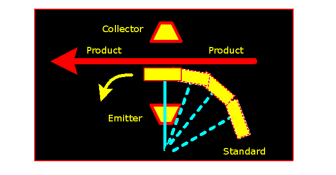
Can a "standard" be inserted into the process, mid-product, on a regular basis?

If so, then fine! The device can be self-calibrating to a certain extent. If it goes too far out-of-wack, then blow the horn.

If not, then possibly the "standard" can be slipped through the measuring point with the product on a regular basis.

The following figure shows a "standard" pivoting through the measuring point with the product at some pre-determined time.
.
.
3d360f99380d189a.gif

.
.
There is a ratio game (not the straight forward kind) to determine the accuracy of the reader. It ain't that tough to figure out if you haven't had too many muscle relaxers - I have.
 
Gentlemen,

I appriciate all your responses and thank you!!

Steve:
You are exactly right in the way the gauge works. We are using a gamma source, not beta, and a gamma source will NEVER weaken in my time, I think it has a half-life of about 250 yrs. The only thing in our enviroment that makes it nescassary to standardize is dirt buildup on the detector and source. dirt build up will give an improper reading of thickness. My application is for measuring steel thickness in a temper mill. I have integrated an old Accuray 7000 into the PLC (kept the cframe and electrometer, and all other functions are done in the PLC), and it works well, there is another gauge on the line to compare with.

The Standardize IS suppose to compensate for dirt errors etc, but im still trying to find a way to determine the noise variations in the electrometer, and track the drift. Standardization cant compensate for that..


Terry:
I understand where you are coming from. But as Steve's response and my response to Steve in this reply indicates, I cant add a standard sample in on the fly. We do though have Satandard samples, which are put though on a regular basis, and track and record the results.

Manojvivek:
Thanks for the reply, I have to think some more about your response, on wheather or not it will acomplish what i want.

Again thanks everyone for their responses, I hope I havn't confused anyone, and HOPE i was clear on what Im trying to accomplish..If anyone has any more ideas, please dont hesitate to post..

Thanks,

Andrew :D
 
If you read his post, he is only talking about the standardization procedure, not about actual process.

I am not familiar with the acutal math that is involved, but I am with some of the terminology. We work with high-precision metalworking tools. For a machine to be accepted it must meet a capability standard. The quality guys use a number called Cpk. Usually a number under 2 is capable. Standard deviation is part of it, but it goes into more depth. It has to do with the shape of the bell curve itself.

You are kind of doing a mini capability study, except that you are measuring your standard every time. You might want to look into the actual math that determines Cpk and implement that. When the number rises too high, set your alarm.
 
Its been a few years, but as I recall the standardization procedure was really more intended to verify that the emitter / receiver combination were still sending and receiving well than to detect build-up. I can see how the two can go hand-in-hand, but I understood this to be less directed toward cleaning and more toward hardware integrity.

In any event (reaching back through the cobwebs) I believe that the typical control systems measures the voltage feedback from the receiver and that a good voltage is about 8.4 V +/- .2 V (my numbers could be off considerably). This is then used as a go-no-go gauge. If you are outside of this range, the standardization fails and the gauge just sits there and stares at you.

Every place I worked where these were used, there was always a preventive maintenance schedule where the gauge was cleaned. The only response to a repeated standardization failure was to replace the sensor.

Using this as a base method, I would suggest monitoring the voltage output of a known good receiver during a bunch of standardizations with a clean emitter / receiver combination and to then use this info to create a similar "good" range. I have my doubts as to whether a full-blown SPC evaluation is really necessary to identify an acceptable range.

Steve
 
Steve,

Thanks for your response.

Yes, the standardization is used to verify that the electrometer is working in a correct range. I have no problem with understanding this concept. I agree with you totally, about replacing the electrometer if the standardize keeps failing. That is one of our practices.

In the old electonic gauge, there was a process/function called a Figure of Merit. This is where my question has arose from.

The Figure of Merit in the old guage is equal to the coeffient of variations of the Anlalog input signal from the electrometer. It provided a way of understanding noise characteristics, in which could be used as a reference point for system degredation.

I am trying to reproduce or come up with a new way of analyzing the noise characteristics.

Maybe I should have put this paragraph in the original post..opps

Thanks,

Andrew
 
Andrew,

While I have worked with an Accuray before (way back when I had hair), I must confess that I cannot recall having heard of the Figure of Merit before.

Just as a matter of interest, I think Accuray was getting out of the business back around 1989 or '90. I am not sure of that, but I do recall having a heck of a time getting support and/or parts back then.

Steve
 

Similar Topics

Hey Guys, Need a little help measuring electrical noise which is causing our encoder reading to flicker. i need help setting up oscilloscope to...
Replies
9
Views
3,185
Hi everyone, I don't know much of PLCs but it happened that i need to connect Leuze AMS358i Ethernet laser measurement to Productivity 1000...
Replies
0
Views
1,066
Hello everyone! Firstly I'd like to say that I'm new to this forum and also new to PLC programming world altogether, that said I really would...
Replies
27
Views
4,856
I am looking for a way to determine level in a silo. The material is called Perilite which has a very light density. Bulk density could be...
Replies
10
Views
2,753
In our water cooling tank, I've installed and successfully wired up 4 float switches & updated the PLC (big thanks to @parky for that). As a...
Replies
46
Views
11,490
Back
Top Bottom