Micro800 PID question

Yashka

Member
Join Date
Nov 2019
Location
WV
Posts
91
Hi All
I'm using Cohen-Coon method to calculate initial PID parameters. So, I have Model Gain that has been calculated from live data. Could anyone explain to me what the value should be set in Kc field of PID_GAINS datatype? Is it ModelGain? Or 1/ModelGain?

Thanks in advance!
 
While I'm familiar with the Cohen-Coon equations for computing PID gains for a first-order with dead-time process, I have never used the Micro800 PID instruction. So, with limited time for investigation, I was waiting for someone else to offer some advice.

After taking a quick look at the Micro800 programming manual, and despite getting somewhat confused by the block diagram in the "How the IPIDController function block implements
PID control," I think I can at least answer your question about how to use the model gain.

Since that IPIDController block diagram shows the error being multiplied by the the controller Proportional Gain (PG), you will want to use 1/Model Gain in the Cohen-Coon equation, which also includes first order time constant and dead time terms, to calculate Kc. That Kc, in units of % per error in PV units, will be the value for the Micro800 Kc (if the published block diagram is complete and correct).

The integral and derivative gains can be more difficult to sort out because the Cohen-Coon results must be consistent with the controller's form of the PID equation (e.g., dependent gains vs. independent, integral time vs. reset rate). The unusual Micro800 PID block diagram implies dependent gains, but the "feedback" nature of the computing the integral term will take some further consideration. Also, with the Ki and Kd specified in units of seconds, they imply the time constant form.

If you use the integral term, take heed of the comment in the manual, which is also consistent with the the integral gain being a time constant: "Increasing Ti decreases the overshoot and oscillation of the PID." That is, a bigger number means less integral.

Thank you for so detailed explanation. But I'm using simple PID instruction, not IPIDController.
 
Thank you for so detailed explanation. But I'm using simple PID instruction, not IPIDController.

I just ran a test of the PID instruction on a Micro820.

  • Proportional action: ∆CV = Kc * ∆(SP-PV) = Kc * Error
  • Integral action: Ti = time in seconds over which a constant Error will generate the same ∆CV (over Ti seconds) as a step change of that same amount of error over one update will generate from Kc.
  • Derivative action: Td = no idea; I did not see any detectable effect on ∆CV from any Td value that I tried.
So it looks like the Micro8xx PID algorithm is implemented like the image below, with the following caveats

  • The Td exception noted above
  • The update time, ∆t, is in the numerator of the Integral term, and presumably in the the denominator of the non-functional Derivative term
  • Source: https://blog.opticontrols.com/archives/383

ideal-1024x486.png
 
So which is it?
Could anyone explain to me what the value should be set in Kc field of PID_GAINS datatype? Is it ModelGain? Or 1/ModelGain?
What are the units?


BTW, Cohen-Coon draws a perfect vacuum. A quarter wave response to disturbances is bad. The Lambda tuning method is much better. There is mathematical justification for lambda tuning ( pole placement ) while there is none for cohen-coon. The same goes for Z-N.
 
Reverse engineering of the CCW PID instruction

For the Micro820 v12 PID instruction, the .Kc member of the PID_GAINS object is definitely gain, ∆CV/∆PV, in CV and PV units, no "percent of range" scalings are used, so if the Cohen-Coon gain calculations are based on CV=0-100% and PV=0-100%, then that gain has to be scaled accordingly for the Micro820 v12 PID. As @Peter Nachtwey asked: what are the units?

The integral behavior is equally straightforward: the .Ti member of the PID_GAINS object is the integral time in units of seconds.

The derivative behavior is convoluted, involving both .Ti and .FC members of the PID_GAINS object. For a step change in PV (i.e. not in SP i.e. in error), .FC expresses a multiple of the proportional response for one update time for that same step change e.g. if PV has a step change ∆PV, so the proportional ∆CV is Kc*∆PV, there is an additive derivative term, .FC*∆CV (=.FC*Kc*∆PV), that becomes part of the total ∆CV for that first update.

The first thing to note is the magnitude of the derivative response is not determined by the .Td member of the PID_GAINS object, as one would expect from the common and conventional [Td*dPV/dt] form of the derivative term; rather the response magnitude is determined by the .FC member, which the CCW PID help documentation calls a Filter Constant. But "What's in a name? that which we call a rose - By any other name would smell as sweet." The second thing to note is that the units of .FC are seconds.

For a conventional derivative term in a PID and a step change, that additive derivative term would disappear on the second and later updates, of course, because ∆PV, and therefore ∆PV/∆t as a proxy for dPV/dt, would be 0 on those subsequent updates.

However, for the Micro820 v12 PID instruction, that additive derivative term instead follows an exponential decay; the time constant (exponent of e) is .Td/.FC in seconds; so the units of .Td are seconds-squared.

This should be enough information to answer OP's original question; if they want someone to tell them what the actual numbers are, that will require a PO.

yyy.png

xxx.png
 
I am looking at the lower right of the top picture where Kc = 0.1 and FC is 4s. That is not a gain. I think you got the FC and Td terms mixed up.
Fc is not defined above. I am assuming it is a low pass filter constant that is applied to the derivative term. This shouldn't be necessary unless the feed back is noisy.


Why does Td have units of s**2?


At the bottom you have 1-exp(-2s/lambda*s)
What is lambda?


@drbitboy, there is no time on the axis x on your charts.


PEOPLE HEED THIS!
in 2005 the control guru
www.controlguru.com
posted some good information. I posted links to it. It seems that it has been ignored because it has gone off the first page of this forum.
However, I still have kept track of the original data.


EVERYTHING can be calculated or estimated close enough. That includes the gains and time constant.
 
Hey Peter.

Thank you for the feedback.

I am not very clever, but I am good with numbers, so rest assured that the central points I made in that post are, I am fairly confident, correct; I will try to resolve your misunderstandings below. That said, I am more than willing to be proved wrong to advance knowledge. So sharpen your pencil ...

The title of that post was "Reverse engineering of the CCW PID instruction." I invite anyone with the time to duplicate my experiments; nothing like the scientific method; if the PID instruction implemented in the CCW Micro850 simulator, then all the relevant software should be freebies.

TL;DR

... That is not a gain. I think you got the FC and Td terms mixed up. ...


Really? Then why does the PV step of -100k, with Kc = 0.1 and FC = 4.0, generate a step of 50k (= 10k[P] + 40k[D]) in the Micro820 v12 PID instruction's CV with a ∆t of 1s? And if I halve that FC, to 2.0, the CV step is 30k (= 10k[P] + 20k[D]).

Do the math: 40k = [0.1 * 4.0 * 100k] = [Kc * FC * -∆PV]; don't assu...

I am assuming

Whoops, too late ;).

Yes,

  • @Peter Nachtwey is assuming the poorly-written CCW documentation is correct and the names of the PID_GAINS object for the Micro820 v12 PID instruction follow the canonical convention;
  • I have measured and reverse-engineered that PID instructions behavior as a synthetic, but (somewhat) deterministic, process, and found a model that is accurate to all five significant digits available in the measurement technique employed.
Who is more likely to be right (that's not rhetorical; measurement is never easy ;))?

That said, I stand by my statements (except for forgetting to label the abscissa), and am confident that what I posted is correct; Peter has merely not grokked it yet.

Why does Td have units of s**2?

  • λ is the time constant of an exponential decay process
    • This is verified by reverse engineering and measureing the behavior, accurate to 5 significant figures, of the Micro820 v12 PID instruction's derivative term after a step change in PV
  • Therefore the units of λ are time, in this case seconds
  • λ = Td/FC
    • Again, verified by reverse engineering and measuring
  • The units of FC are seconds
    • The quantity FC in the Micro820 v12 PID is what is usually called Td in the canonical PID formula
      • Again, verified by ...
  • ∴, Td = λ FC
  • ∴, the units of Td are s*s => s**2
At the bottom you have 1-exp(-2s/lambda*s)
What is lambda?

[Update: in the post that denominator of the exponent is "λs" not "λ*s;" the "s" was a clumsy attempt to express the units of λ]

Arrgh, should have used τ, although then there might be confusion with deadtime. Anyway, λ is the time constant of an exponential decay process (I am sure that is obvious from that formula, but I want to state it explicitly). Also,
λ = Td/FC
So, in the example shown in previous post #8:
λ = (2.6667 / 4.0) = (2/3)s
@drbitboy, there is no time on the axis x on your charts.

Ouch, yes, my bad, I meant, but forgot, to put a pair of dimensional arrows indicating the scale of 1s; however note that ∆t is 1s (cf. annotation in lower right), and know that the visible steps of the CV decay therfore occur at intervals of 1s (∆t); also note the annotation. (3) and (4), of the time of each decay step.

P.S. I feel like Captain Queeg: "They laughed at me and made jokes, but I proved beyond the shadow of a doubt and with - geometric logic ..."
 
Last edited:
Wow!
It's amazing! :) I've saved this thread for future more intensive study. (y)

So, I've resolved this issue via a lot of experiments. According to my results of those tests, Kc is Model Gain, no 1/Model Gain.

Thanks to all for the help!
 
You guys are copying without understanding.

Wow!
It's amazing! :) I've saved this thread for future more intensive study. (y)

So, I've resolved this issue via a lot of experiments. According to my results of those tests, Kc is Model Gain, no 1/Model Gain.

Thanks to all for the help!


NO! NO! NOOOOOOOOOOO!
Look at the diagram that drbitboy posted. Kc is the controller gain. The control gains has units of %output/error unit. The model gain is K and has units of PV units/%control output. If this system is a temperature system and the gain is 3 degrees/%control output then an output of 50% would raise the temperature by 150 degrees over ambient. You can do this open loop. It is that simple.


Really? Then why does the PV step of -100k, with Kc = 0.1 and FC = 4.0, generate a step of 50k (= 10k[P] + 40k[D]) in the Micro820 v12 PID instruction's CV with a ∆t of 1s? And if I halve that FC, to 2.0, the CV step is 30k (= 10k[P] + 20k[D]).
Is that step -100 degrees Kelvin or 100 thousand? 100 thousand is a very big number. How does the PV magically make a step?
I understand the control output can make a step or the set point can make a step but nothing responds instantly.


What you are saying doesn't make sense at all.


You are misusing λ.

Usually control books use tau, for time constants. Lamda,λ, is used as in Lambda tuning where λ is where the closed loop pole is located. While Lambda is positive, the closed loop pole location is placed at -λ . λ can be a complex number.


Dead time is usually shown as θ or θp for plant dead time.


What is CCW?


Td should have units of time, not time^2. The derivative gain is effectively Kc*Td and is multiplied by the error in the rate of change of the PV. YOUR UNITS WILL NOT CANCEL OUT!


This is how you do it.
https://deltamotion.com/peter/Mathcad/SOPDT/Mathcad - SOPDT1.pdf


I show how the controller gain and time constants are derived and account for the dead time. In my example tauc is set at equation 21. Making tauc shorter makes the the response faster by increasing the controller gain, Kc.
In my example the PV, temperature, does not make step jumps. I added a little randomness to this example to simulate real conditions.


The PID or I-PD in this case is implemented in equation 29. The derivative time constant is multiplied by the rate of change of PV or temperature. My units work.


This example was done for the www.controlguru.com site back in 2005 but it was never used. Only my FOPDT example was used because it is simpler. My FOPDT example was for a heat exchanger simulation.
 
@Peter - you are not paying attention. It does not matter a fig what the conventional meanings and units of Kc, Ti, Td and FC are; OP was asking about Micro800/CCW (see below) minutiae, and I provided correct information that makes sense in that context. This is an insane alternate universe defined by Allen-Bradley (no big surprise there), so try to keep up; stating the conventional meaning of Td et al. is irrelevant and less than useless; think Rod Serling and The Twilight Zone.

TL;DR


What you are saying doesn't make sense at all. ... What is CCW?

Sigh. You have no idea of the context of the thread yet you think what I wrote makes no sense; could those two facts be related ;)?

CCW is Connected Components Workbench - the Allen-Bradley morass of "software" used to program the Micro800 series of PLCs, which is the context for this thread (cf. Post #1 title).

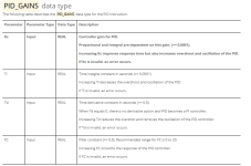
The PID instruction in CCW (see above) uses an input object of datatype PID_GAINS to determine the P, I, and D responses. That object has four parameters, per the following (not very) "help" (-ful) documentation delivered with CCW (see above):

ccc.png

My point and claim is that ALMOST ALL OF THOSE DESCRIPTIONS ARE WRONG in a MicroC00/CCW context, and the canonical conventions are useless. The actual behavior of the PID instruction supports the following statements:

  • PID_GAINS.Kc is controller gain in units of ∆CV/∆Error, not ∆%CV/∆Error,
  • PID_GAINS.FC is the derivative time, its units are seconds.
  • PID_GAINS.Td combines with PID_GAINS.FC to define a filter time constant (τ) used to generate the PID instruction's CV output. Since .TD/.FC is that time constant in seconds, .Td must have units of seconds squared (don't try to debate unit analysis with me; you'll get buried).
All of those statements are based on the behavior of the PID instruction "controlling" (i.e. responding to) a synthetic process that I controlled manually via the CCW (see above) interface. You and anyone else are more than welcome to download the CCW Standard Edition freebit and see if you can replicate my experiment.

You are misusing λ.

I already addressed that; I defined what it was so the symbol I used is irrelevant; "a time constant by any other name would smell as sweet." Post-modernism is ludicrous in general, and has no place in this forum specifically.

Is that step -100 degrees Kelvin or 100 thousand?

1) You're trolling me here, am I right?
2) I wrote -100k i.e. lowercase k, not -100K i.e. UPPERCASE K, so it is -100,000, not -100 Kelvins.
3) There is no such thing as "degrees Kelvin"
 
@Peter - you are not paying attention.
I am. I am trying to set you strainght.

It does not matter a fig what the conventional meanings and units of Kc, Ti, Td and FC are; OP was asking about Micro800/CCW (see below) minutiae, and I provided correct information that makes sense in that context.
It does make a difference.

This is an insane alternate universe defined by Allen-Bradley (no big surprise there), so try to keep up; stating the conventional meaning of Td et al. is irrelevant and less than useless; think Rod Serling and The Twilight Zone.
There is nothing wrong with Rockwell's definition of Td. Normally it defined in minutes but seconds will work too.

Sigh. You have no idea of the context of the thread yet you think what I wrote makes no sense; could those two facts be related ;)?
If you know the unit of the gains then you can determine the answer. The open loop gain, K, is always in the denominator of the controller loop gains. It should make sense that the large the open loop gain is the smaller the closed loop gain needs to be. This is something that has gone over everyone's head. I can/have proved it. I can derive the formulas for controller gains. They can be calculated!!


CCW is Connected Components Workbench - the Allen-Bradley morass of "software" used to program the Micro800 series of PLCs, which is the context for this thread (cf. Post #1 title).
OK, now I know. I/we usually deal with RSLogix softare.

My point and claim is that ALMOST ALL OF THOSE DESCRIPTIONS ARE WRONG in a MicroC00/CCW context, and the canonical conventions are useless. The actual behavior of the PID instruction supports the following statements:
The definitions look fairly standard to me. Are you saying the Micro800 doesn't implement them correctly? If find that hard to believe Rockwell would screw up that badly.

PID_GAINS.Kc is controller gain in units of ∆CV/∆Error, not ∆%CV/∆Error,
What are the units of ∆CV? It is just a difference in scaling.

PID_GAINS.FC is the derivative time, its units are seconds.
Above it says it is a filter time constant. This makes sense to me. See my Taulpf low pass filter formula 19 and implementation in equation 28. The Fc is a low pass filter is a time constant.

PID_GAINS.Td combines with PID_GAINS.FC to define a filter time constant (τ) used to generate the PID instruction's CV output. Since .TD/.FC is that time constant in seconds, .Td must have units of seconds squared (don't try to debate unit analysis with me; you'll get buried).
Td doesn't combine with FC the way you think. Your example has units of s**2 which is very wrong. The picture of the controller doesn't show how FC is used. It could be used to filter the feed back for all the gain or just for the derivative term. However, if is a low pass filter and it not simply multiplied by Td.

All of those statements are based on the behavior of the PID instruction "controlling" (i.e. responding to) a synthetic process that I controlled manually via the CCW (see above) interface. You and anyone else are more than welcome to download the CCW Standard Edition freebit and see if you can replicate my experiment.
T
the one were the PV make a huge negative step? What reality do you live in?
My simulations are realistic. I have done them for the department of energy


1) You're trolling me here, am I right?
I am trying to set you straight and keep you from misleading the forum.

2) I wrote -100k i.e. lowercase k, not -100K i.e. UPPERCASE K, so it is -100,000, not -100 Kelvins.
So what jumps -100,000?


3) There is no such thing as "degrees Kelvin"
[/quote]
0 degrees centigrade is 273 degrees Kelvin. The Kelvin scale is absolute whereas centigrade is relative to the temperature where water freezes. Look it up.

A low pass filter in the s domain is 1/(FC*s+1) where FC is a time constant and s is the Laplace operator that has units of frequency (jω). The two terms, FC and s have units that cancel each other out so that the result is just a complex number that has a magnitude or gain and phase.

I prefer implementing the low pass filter on the output.
https://controlguru.com/pid-with-controller-output-co-filter/
The controlguru site is a very good site to learn from.
 
Last edited:
I am. I am trying to set you straight.
@Peter: I appreciate that. I really do. I sense no malice in your posts, only good will; I hope you sense the same in mine. But while you are probably often the smartest person in the room, that does not mean you know what room you are in.

I have for decades understood, and tried to follow when I could, all of your assumptions, about units, about the conventional meanings of the symbols K, Kc, Ti, Td, FC, τ. etc., which would be useful in a conventional conversation. But they do not apply here.

My point and claim is that ALMOST ALL OF THOSE DESCRIPTIONS ARE WRONG in a MicroC00/CCW context, and the canonical conventions are useless.
The definitions look fairly standard to me. Are you saying the Micro800 doesn't implement them correctly?

For the love of all that is holy and as I have been telling you for some time now: Y. E. S. I.e. YES, Micro800 doesn't implement them correctly.

You are getting close; dare I deign to think I see light at the end of the tunnel? ...

If find that hard to believe Rockwell would screw up that badly.
... aw krap, apparently not. Also apparently you have never used CCW before, else you would not cling to that belief.

Don't be misled by your presuppositions!

Drop that assumption, i.e. that the usually stellar A-B documentation is accurate in this case, and look at the data i.e. how the CCW/Micro800 PID instruction actually performs.

Cf. the hand-annotated trend plots in Post #8:

  • they contain hard data from a Micro820 PLC in Run mode
    • running a program with a PID and little else,
    • The PID update time is 1000ms, executed via STI (timed interrupt on a 1000ms cycle).
  • The PV and SP inputs are but numbers
    • PV has no physical process behind them
    • They can only be changed manually
      • using CCW
        • Connected to (in Online mode with) the Micro820.
  • The CV is also but a number
    • that the PID generates
    • and is then trended
    • it does not affect the PV at all,
  • It is setup this way because I am only interested in reverse engineering the black box called "CCW/Micro800 PID"
  • The pidgains tag is a PID_GAINS object with four members
    • Kc - set to 0.1
    • Ti - set to 1E+30
      • i.e. infinity,
      • so if the standard convention applies, there will be no Integral action, or at least it will be to small to show up in the 32-bit REAL CV output
    • Td and FC
      • These seem to have something to do with Derivative action.
      • I can vary these manually, the same as I do with PV.
  • The horizontal axis is time, with a 10ms nominal sample time,
    • but CCW seems to see updates every 200ms or so.
  • At the start of the trend, PV and SP are 0.0, CV is also 0.0
    • Remember that PV is not attached to a process, so it is always at steady state,
      • no matter what the PID does with CV,
      • and unless I change PV manually.
  • At the time of vertical red line, the trend algorithm detects that CV increased above some trigger level
    • The CV change was caused by the PID algorithm responding to a change in the PV some time during the ~1000ms before the red line.
      • The PV change was from 0 to -100k (100,000)
      • That change was does manually by my own little fingers.
      • SP did not change, so Error changed from 0 to 100k
        • or maybe -100k; the sign convention inside CCW/Micron800 PID is hidden
    • The trend software is configured to show a few seconds of pre-recorded, pre-trigger data, to the left of the red line.
  • The CV jumps to 50k (50,000)
    • And decays down toward 10k (10,000) over the next dozen or so seconds.
  • From previous experiments, if pidgains.Td and/or pidgains.FC were 0, which disables Derivative action, then CV would have jumped to 10k and stayed there.
  • The eventual 10k result for CV is consistent with Kc (0.1) being controller gain, with units of ∆CV/∆Error ~ ∆CV/∆PV
    • Without the CV output filtering but with any amount of conventional Derivative action, the CV would return to 10k on the second update after the step change in PV and Error.
    • From other experiments with different Kc values, all actions, Proportional and Integral and Derivative, are linearly affected by Kc.
  • From similar experiments with other values in pidgains, I can confidently state that
    • The initial, first PID update kick in CV is a function of pidgains.Kc and pidgains.FC only
      • pidgain.Td has no detectable linear effect on this initial kick witha 1000ms PID update time
        • I did see some effect in the CCW trend when I had a shorter PID update time of 100ms
          • but I suspect that was because the PID had executed two or more updates by the time CCW saw any change in CV output
            • Cf. the comment above about nominal update time of CCW trend
      • pidgains.Td does affect the decay of the CV output toward its eventual (Kc * ∆Error) result
        • The numerical analysis shown to the right of the trend, where (pidgainss.Td/pidgains.FC) is the exponential time constant τ, is consistent across various values for pidgains.Td and pidgains.FC
Anyone is welcome to attempt replicating this experiment; I will learn more by being wrong than by being right, but so far I have seen nothing to suggest the former and all data, other than unsupported assumptions, telling me the latter.

You read this far? Impressive; I will use the event to remind you that this experiment is specifically not about conventional PID notation; rather it is about reverse-engineering the PID implementation specific to CCW/Micro800 PLCs, using as few presuppositions as possible, with an ultimate goal of helping the OP convert Cohen-Coon results into the PID_GAINS object of a Micro8000 PID.
 
Last edited:

Similar Topics

So I am using a Micro850 and I downloaded the RA_PID UDFB for tuning the temperature of my Thermocouples(TC). I am not sure if I am using enough...
Replies
0
Views
1,431
Can someone tell me what i am doing wrong here? I have set the limits of the CV value for 5min and 60max. The output of the PID is not staying...
Replies
1
Views
1,593
Hi there, I have a small heating system with a micro 830 PLC to assist with the learning process of automation and PLC's etc. The system is a...
Replies
11
Views
8,307
My company built a small test machine using a Micro800 PLC and CCW software. We chose the Micro800 because the machine is very simple. We are...
Replies
2
Views
147
Back
Top Bottom