Mitsubishi inverter with Renu PLC

advmin

Member
Join Date
Mar 2023
Location
Sheffield
Posts
59
Hello all,

Inverter/VFD : MITSUBISHI FR-D740-036-EC (3 phase,400V)
PLC: RENU FL0050808402U

I am trying to connect the RENU plc with the inverter using RS 485.
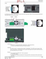
In the PLC there are two ports in which only the 4-pin terminal (COM 2) supports the RS 485, and COM 1 ( RJ-45) only supports RS -232, so COM 2 is the only way to communicate with the inverter since the inverter didn't support RS 232.

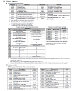
The port on the inverter is RJ-45 which supports RS-485.


Please provide any pinout for making a cable with one end RJ-45 and the other end for 4 pin RS 485.

I am confused because pinouts vary with different websites.

I have attached the snippets of the inverter and plc. Please have a look.

cheers

inverter mits rs 485.jpg PLC renu.jpg
 
Thanks, Parky for the quick reply.

I don't understand much from the link you shared.
I cut down an RJ-45 cable on one end and there are 8 wires, in which I shorted positive ( 3 and 5) connected to A, negative ( 4 and 6) to B, ground (1 and 7)to GND, and (2 and 8 ) to not connected (NC) of 4 pin terminal at plc end, according to the pin out in the snippet I attached before.
 
I cut down an RJ-45 cable on one end and there are 8 wires, in which I shorted positive ( 3 and 5) connected to A, negative ( 4 and 6) to B, ground (1 and 7)to GND, and (2 and 8 ) to not connected (NC) of 4 pin terminal at plc end, according to the pin out in the snippet I attached before.
That sounds like the proper wiring. However, if communication is not working, keep in mind that the A and B labeling of RS-485 signals is not universal. Some vendors use A for positive, while others use B for positive. You may need to swap your positive and negative wires (i.e. connect the positive wires to B and the negative wires to A).
 
What it shows is linking the TX+ to the RX+ & The TX- to the RX- on one side of the 4 wire plug, the other end only has TX/RX
See here perhaps a better explanation you will probably need 120 ohm termination resistors at each end like shown in the first link I showed you, however, sometimes an echo occurs where a reply is sent when not required so in these circumstances you need a converter 4 wire to two wire. 4 wire is normaly full duplex, 2 wire is half duplex.
look at this link it might explain a little more
https://electronics.stackexchange.c...re-rs485-2-wire-device-to-rs485-4-wire-device
 
You only need termination resistors for long cable runs and high baud rates (this is done to eliminate transmission line effects, i.e. signal reflections). And it may not always be 120 ohms - it needs to match the characteristic impedance of the RS-485 cabling used. Adding termination when it is not needed can actually cause communication problems for some devices if you are not also adding biasing resistors (the termination resistors can cause the differential idle voltage to fall into the 200mV "undefined" range).


Here are a couple references on termination:
https://e2e.ti.com/blogs_/b/analogw...nation-is-necessary-and-how-to-do-it-properly


https://blog.opto22.com/optoblog/rs-485-to-terminate-bias-or-both


Incompatibilities between 4-wire and 2-wire RS-485 usually come down to software, in that the 4-wire device is always receiving. When you connect the transmit wires to the receive wires, the 4-wire device receives its own transmissions and can misinterpret these as requests and go off into a communication loop with itself or at the very least cause its receiver state machine to be out of sync.


Even though 4 wire is capable of full duplex communication, that feature is rarely utilized and must be supported by the protocol in use. Since this is (presumably) Modbus RTU, it is a half-duplex protocol (request and response).


I've worked with the Mitsubishi 700 series inverters and they have no problem connecting to a 2-wire RS-485 device.
 
Thanks everyone for the replies.

You may need to swap your positive and negative wires

I shorted positive ( 3 and 5) connected to A, negative ( 4 and 6) to B, ground (1 and 7)to GND, and (2 and 8 ) to not connected (NC) of 4 pin terminal at plc end

I swapped the positive and negative. Then, I disconnected all the wires from GND and NC. Now I have the wire communicating ie, the NET option over the inverter is lit.

I never worked on Modbus,
Here I am using FLEXISOFT ( software) with RENU PLC.
I read through the d740 manual but couldn't find an idea on mapping.
I configured the network MODBUS SLAVE in COM 2. I added it as NOD 1.
When I tried to add TAGS it said MODBUS REGISTERS ARE MAPPED WITH DEVICE REGISTERS.
Please provide some guidance on how to control the inverter using MODBUS.
Is it similar to the relay coils that we are using in usual ladder programs?

I have attached the images of tag addresses in the inverter and plc.

Please have a look

cheers

INVERTER MOD.png RENU MOD.jpg
 
A couple comments on the wiring.


Don't disconnect GND. This is the signal (0V) reference for the + and - lines. You want both devices to share a common reference.


Don't land pins 2 and 8 from the VFD to the NC terminal on the PLC. The NC terminal on the PLC is likely for shield daisy-chaining. The wires for pins 2 and 8 should be cut off or taped back.


Regarding the configuration of the PLC, the PLC needs to be configured as a Modbus RTU master (since the VFD is a Modbus slave). Two slaves cannot communicate to one another. Once you have configured the PLC to be a master, there should be a way to target the slave address of the VFD and map the registers on the VFD to the PLC (possibly to tags).


Note that the VFD uses 5-digit reference notation for Modbus register numbers (i.e. 40010 means Holding Register 10), while it seems the PLC uses 6-digit reference notation (i.e. 400010 means Holding Register 10).
 
Thanks jschulze for the reply.

I have referred a lot over this topic, but still couldn't able to make the inverter run through Modbus.

In Rockwell, there is a dedicated MSG option to map the Modbus with plc tags.
But here in RENU plc ( flexisoft software), it shows that default registers are there for mapping.

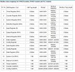
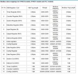
As per the PLC,
HMI Register / Coil - Timer Register (R/W)
HMI Tag length - 2 Bytes
Range - 0000-0255
Modbus Mapping - 400001 - 400256
Modbus Tag Length - 2 Bytes

As per the inverter documentation,
Set Word 40009 = 0000 0000 0000 0010 = 2 >>> Forward Run
Set Word 40009 = 0000 0000 0000 0100 = 4 >>> Reverse Run
Set Word 40009 = 0000 0000 0000 0000 = 0 >>> Stop

What things do I need to make the inverter running? (I have set all parameters in the inverter according to the documentation )


cheers

RENU MOD.jpg
 
The registers you're referring to for the PLC are only for when the PLC is configured as a Modbus slave. The PLC can be configured to be either a slave or a master. You need to configure it to be a master.
 
Thanks jschulze. I made the plc as master and also there is a dedicated TASKS section in Flexisoft in which we can map the Holding registers to the data register. It took me some time to spot that. Now everything is running well.
These data registers can be used in the program to control the inverter.

Thanks again for the guidance.

cheers and have a great weekend.
 

Similar Topics

I have Toyopuc PLC PC10G-CPU and some communication modules of it. With this modules I'm able to connect with Ethernet, Ethernet/IP, FLnet, FRMT...
Replies
0
Views
94
Hello I am writing to request assistance with obtaining a specific GSD file for our Mitsubishi inverter type A800-E, which is connected to our...
Replies
12
Views
431
Hi, I am trying to create a program for the 5U that can communicate to 2 or 3 VFDs (individual control, not broadcast) using the inverter...
Replies
0
Views
1,034
Evening all, Currently stuck in the office trying to get a working bit of program together for a Mitsubishi FX3G to control two FR-D720S...
Replies
1
Views
1,686
F540 22KW Cor, I've struggled with this. Can anyone tell me what I am missing. Customer bought a 2nd hand inverter as above (old one blew up) -...
Replies
10
Views
3,009
Back
Top Bottom