Mitsubishi Q series: Another SET/RST logic question...

Mas01

Member
Join Date
Oct 2020
Location
Leicester, England
Posts
1,109
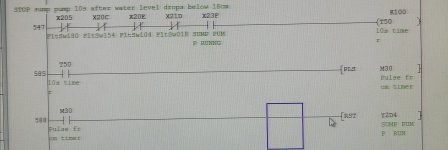
We've got a sump pump which is switched on/off at the HMI by clicking a button on the screen then a physical pushbutton on a console, using this code. The code works fine for starting/stopping the pump (see Step 1034/1070)


We've also got another step in the code where the pump will automatically turn off if the water level is below 18cm (to prevent damaging the pump). See step 547 onwards.

HOWEVER, as the code stands, once the pump turns off due to the low water level, it does not turn back on once the water level starts rising again (and this is a requirement)

I'm not sure how to include the "low water condition" into the start/stop logic so that there is only one SET and only one RST instruction for this pump.

Can anyone help? Thanks in advance.

IMG_20220408_163441.jpg IMG_20220408_163152.jpg
 
You need a latch for the start/stop then use say two timers so that when the level drops below the low level for 10 seconds it inhibits the pump but when covered for 10 seconds (stops hunting) re enables the pump.
as code below.
 
This may do what you want. Caveat: I do not know the process. the new branch may need to go around the [M413 SumpPumpSeltr] NO test as well*.

P.S. I would also combine the two rungs (588 and 1073) that stop the pump, to there is only one [RST Y2D4] instruction; that way it's easier to find where the pump is being turned on or off. When debugging you can search for the FltSw018=>T50=>M30 chain later, or move the <T50=>[PLS M30]> rung between the SET and RST.

* P.P.S. I don't know what [M413 SumpPumpSeltr] is about, but if it selects which pump should be running, then you may want to have a [NC SumpPumpSeltr] feeding the [RST Y2D4] as well, to ensure this pump is turned off when this pump is not selected.


P.P.P.S I don't know what M32 is about, but as it seems to be a pulsed bit i.e. true for one scan based on some unknown logic, it does not make sense to put it in series with the motor start pushbutton(?).


IMG_20220408_163441.png
 
Last edited:
Also, I have to ask, what is the purpose of FltSw180, FltSw154, and FltSw104 in the [SET Y2D4] rung?

Assuming

  • FltSw018 is the 18cm float switch, and
  • The value of FltSw018 is 0 when the level is below 18cm, and
  • All those other float switches (FltSw180, FltSw154, and FltSw104) are above FltSw018 and have the same polarity (0 for level below, 1 for level above),
then surely all of those other float switches will be 0 whenever FltSw018 is 0, n'cest-ce pas? Or is this some kind of "we don't want a faulty level switch at 18cm to override any of the other switches that indicate the level is higher?"

You are correct, they are all float switches. As we say in British English, it's a bit "belt and braces" (suspenders, to you), it's an extra security in case the 18cm float switch is faulty for whatever reason.
 
This may do what you want. Caveat: I do not know the process. the new branch may need to go around the [M413 SumpPumpSeltr] NO test as well*.

P.S. I would also combine the two rungs (588 and 1073) that stop the pump, to there is only one [RST Y2D4] instruction; that way it's easier to find where the pump is being turned on or off. When debugging you can search for the FltSw018=>T50=>M30 chain later, or move the <T50=>[PLS M30]> rung between the SET and RST.

* P.P.S. I don't know what [M413 SumpPumpSeltr] is about, but if it selects which pump should be running, then you may want to have a [NC SumpPumpSeltr] feeding the [RST Y2D4] as well, to ensure this pump is turned off when this pump is not selected.


P.P.P.S I don't know what M32 is about, but as it seems to be a pulsed bit i.e. true for one scan based on some unknown logic, it does not make sense to put it in series with the motor start pushbutton(?).


View attachment 61691

M32 is a bit which is set when all 4 float switches are false (meaning the tank is empty). i.e. we don't want to start the pump if the tank's empty.

M413 is a bit associated with a mouse button click, when you click on the name of the pump that you want to start/stop....starting a pump is a 2 step process, you click on the name of the pump you want to start (this setsM413) then you press a physical button X213 to start the pump.
 
Last edited:
You need a latch for the start/stop then use say two timers so that when the level drops below the low level for 10 seconds it inhibits the pump but when covered for 10 seconds (stops hunting) re enables the pump.
as code below.
I "think" I understand this but I've got a few questions based on your code. Please take a look at the attached.

Questions.PNG
 
You are correct, they are all float switches. As we say in British English, it's a bit "belt and braces" (suspenders, to you), it's an extra security in case the 18cm float switch is faulty for whatever reason.

Bottom line: the logic prefers a low level (pump cavitation) than a high level (overflow?). Do I have that right?

TL;DR

So it protects against the logic turning the pump off when FltSw018 is 0, indicating that the level is below 18cm, if any of the other higher level switches indicate the level is above that higher switches level.

That works if the 18cm switch's signal is in error and the rest are correct. However, it also prevents the logic from turning the pump off if the 18cm switch's signal is correct and 0 but one of the other level switch's signals is in error and stuck at 1.

(P.S. I know what braces are, and I like to wear them with my belt;))
 
The problem is without a seal in bit like I posted, the low level pulse bit will reset the pump, however, because the original start button will not be on there is no way to restart it without pushing the button again, if you follow what I did it will work so what it actually does is sets a bit (seal in if you like) this stays active true until the stop button is pressed, the two timers then give a slug time on the low level probe so when the level drops below the low level after 10 seconds the pump will stop because the interlock will energise, on reaching low level or above for 10 seconds the pump will re-start because the original start/stop latch will still be active.
 
Yes they are M bits, well the top one is, the timer contacts are actually the timer contact not M bits I will quickly throw a GXDeveloper one together that will make more sense. The output is just a coil no set or reset.
I do not like set/reset of coils because on some code it may be required to turn the pump on or off many times this becomes confusing if for some reason the pump will not run, it shows the conditions on the pump logic & you just do a cross ref of the bits driving it & work back.
 
Last edited:
M32 is a bit which is set when all 4 float switches are false (meaning the tank is empty). i.e. we don't want to start the pump if the tank's empty.

So M32 is the same as the Normally-Closed instructions on the four level switches ANDed with [X23F SUMP PUMP RUNNING] at rung address 547.

Applying DeMorgan, that means the RST at rung address 1037 cannot execute unless at least one of the level switch bits is a 1. I.e. the following two are equivalent:

  • M32 := (NOT FltSw180) AND (NOT FltSw154) AND (NOT FltSw104) AND (NOT FltSw018);
  • M32 := NOT (FltSw180 OR FltSw154 OR FltSw104 OR FltSw018);
M413 is a bit associated with a mouse button click, when you click on the name of the pump that you want to start/stop....starting a pump is a 2 step process, you click on the name of the pump you want to start (this setsM413) then you press a physical button X213 to start the pump.

So although M413 is clicked based on the choice of a pump, and it multiplexes a button press event to control "something" about that pump, it does not feed into that "something" itself; i.e. the value of M413 never by itself determines whether the pump itself is running.
 
Forgot to add, but not sure what happens if the safety relay (E-Stop) is pushed, but normally, you would reset any latches so things do not re-start on clearing the e-stop, in other words it requires an operator intervention to re-start the system for safety reasons possibly, this is normally done by the monitor contact of the e-stop system to a PLC input.
 
I understand that M413 controls which pump turns on or off when the start or stop pushbuttons are pressed.

But what would control which pump should turn on when the level goes above the 18cm switch?
 
DR, that was my point it cannot as he is using the manual start/stop directly on the pump output it cannot re-start, that's why it needs a memory so that after being started it knows so then it will control on the level, personally I would stop the pump on low level & not re-start until it is on the next level up (I'm assuming this probe has 4 levels) i.e. low low low, high, high high.
Also, I noticed he has put all levels in the logic, I have not shown that just the low level, if there was a fault on one level i.e. stays on (effectively illegal combination) it will not switch off, in this case I would do the combination logic to produce an alarm on illegal pattern of the levels & shut the pump off.
 

Similar Topics

Hi, Can someone help me by explaining how I can transfer data from one PLC to another. I'm using GX Works 2, both CPU's are the same (Q03UDVCPU)...
Replies
6
Views
2,375
Ok, I'm using an A2USH series plc and I was looking for the one-shot rising and one-shot falling instructions and noticed that they were not...
Replies
7
Views
3,819
how to communicate FactoryTalk Optix and Mitsubishi Q Series. I want to know the details of that
Replies
0
Views
37
In this sample programming, what does U4 mean? Any assistance would be greatly appreciated.
Replies
8
Views
273
Back
Top Bottom