Modscan return value conversion

derickloo

Member
Join Date
Mar 2015
Location
Malaysia
Posts
36
I have a Type C to RS485 adapter connect to my Siemens RWF55. I use modscan to scan it to get a value from the Siemens controller. In the controller, I have a thermocouple connected and the temperature show on screen was 37 degree.
When I modscan to scan it, in the address 40002, the value was 16916(unsigned decimal set in Modscan). What is unsigned decimal and how I can convert it back to 37 degree celcius?
 
The unsigned 16-bit register value of 16916 contains the high (most significant) 16 bits the 32-bit IEEE-754 single-precision floating-point value 37.0*. To get the full value, you will also need the Holding Register at the next** address ("4"0003**), and then copy the bits (not the values) of those two Holding Registers into a REAL tag.

The details of how to accomplish that will be specific to the operating and programming environment and capabilities of the whatever device is reading the Holding Registers. E.g. perhaps Modscan is a PC program? If so, maybe Modscan has an option to interpret the bits in pairs of adjacent Modbus registers as the bits of 32-bit floating-point values.

* the floating point value could be anything in the range [37.0:37.25), depending on the bits in the second 16-bit register.

** Note that you should be careful to ensure that the single floating-point value indeed comprises the register pair "4"0002 and "4"0003 (Most-Significant Word-First), because it is possible that the correct pair could be "4"0001 and "4"0002 (Least-Significant Word-First).
 
Does Modscan allow you to read register "4"0000? If yes or no, then transfer the first 8 registers starting at "4"0000 or "4"0001, respectively, and post a screenshot here.

Does Modscan display the Tx and Rx buffers it transmits via RS-485? If yes, please include those in the screenshot above.

Because if the first register Modscan can read is "4"0001, and you want to read RWF55 Analog Input InP2, then you actually want to read the two Holding Registers "4"0003 and "4"0004 (or "4"0001 and "4"0002 for Analog Input InP1). Cf. here.
 
The User level table is from an RWF55 manual.
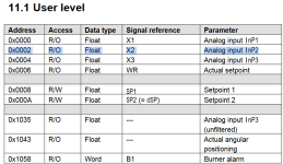
RSF55 register table.png

It shows analog input 2 as residing in address0x0002 as a floating point value.

Let's assume these are Holding Register addresses (manual doesn't say) because you got a valid reply in Modscan when querying (4)0002

The table says the value is floating point value, which means it is a 32 bit value that use two 16 bit Modbus registers. You need to use the function in Modscan that interprets the value as a floating point, and you'll be able to read the value directly.

It is not possible to obtain a valid integer value from only one 16 bit register of a 32 bit floating point. You need all 32 bits to make sense of the value

You also need to read the correct register and correct number of registers

The hex registers are zero based, but Modscan is one based, using xxxx part of a (4)xxxx notation in the Modscan's "Address" text entry box
0x0000 = (4)00001 = analog input 1 (first 16 bits of the floating point)
0x0001 = (4)00002 = 2nd 16 bits of AI 1's floating point value
0x0002 = (4)00003 = analog input 2 (first 16 bits of the floating point)
0x0003 = (4)00004 = 2nd 16 bits of AI 2's floating point value

So to read AI 2 as floating point (FP) value in Modscan,
- configure your Device ID
- select 03 Holding Register as Modbus point type
- configure the Address as 00003 and Length 2 (which reads two registers, starting at (4)00003)
- select one of the two Floating point buttons, circled in red. One is FP, one is swapped FP, either uses different word/byte order to interpret the FP value
and the FP value will appear in the work area next to 40003: xxxx s
If the value is reasonable, that's the correct FP button.
If the value is ridiculous, that's the wrong FP button, try the other one.
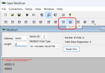
Modscan reading 40003 AI 2 as FP-hi.png
 
If the value is reasonable, that's the correct FP button.
If the value is ridiculous, that's the wrong FP button, try the other one.

This is the bit that makes it art.

There are only 24 possible orders of the four bytes in a 32-bit float, and five-sixths(?) of those are ruled out (usually) because byte order and word order are the same in INTs and REALs on the device, so it's down to 4. If the device implements Modbus correctly, byte order within words is handled correctly, and it's down to two possibilities.
 

Similar Topics

Hi everyone, I'm trying to simulate any program in control expert and see a register in Modscan32 or any software to do that (Like ModbusPoll). I...
Replies
0
Views
95
Dear All, I could not get the results with modscan software to test the Modbus connection for the digital relays. The modscan software says...
Replies
3
Views
4,917
Good Day, I'm using Mod Scan 232 for testing a Modbus RTU network on RS 485. The modbus device is Accuload iii.net. The connection settings on...
Replies
1
Views
4,177
I am trying to integrate Power Logic PM750MG with my RTU. My RTU cannot read the C phase-neutral or C-A phase to phase voltage. If I use modscan...
Replies
5
Views
2,137
This is for editing HMI texts en masse in Excel. My problem is that in my HMI texts, some are in multiple lines, even if they are single texts...
Replies
26
Views
9,149
Back
Top Bottom