PID Smith predictor

Huh? That is off (low) by nearly three orders of magnitude.

Speed of sound on a fluid is sqrt(K/rho), K is bulk modulus of elasticity, ~2e9Pa, rho is density, ~1e3kg/m**2
You are right. That should be per millisecond. I also know that it isn't exactly 4ft/msec but if it close enough. What irks me is that people have put 40ft of hose between the valve and piston and wonder why the system is difficult to control.
 
@Pandiani: I read the article. It is very interesting. But my problem is how to use it in a PLC? I am looking forward to that example with a PID controller combined with the Smith predictor.

Is it possible to do moddeling without step response in a PLC? Just by looking at the CO, PV & SP.
 
@Pandiani: I read the article. It is very interesting. But my problem is how to use it in a PLC? I am looking forward to that example with a PID controller combined with the Smith predictor.

Is it possible to do moddeling without step response in a PLC? Just by looking at the CO, PV & SP.

I really think you should take more time to study and understand how FOPDT is implemented. Then you would probably figure it out how to make the Smith predictor implementation in the PLC.

Anyway just for the exercise and education ONLY, I have attached the source code as well as an example of OB35 calls. Like I said, it is only for demonstration purpose, made to be used in PLCSIM and not in the real world. However theory works and it can be used in the real world but only after you have a full understanding what is going on and of course use it at your own risk.

There are three files attached:
1. The structure of the Smith predictor block diagram that needs to be implemented and simulated in the PLC. In reality you'll not have FOPDT structure in your PLC program, that would be a real world system you're trying to control.
2. The source code of the Smith predictor implementation
3. An example of OB35 call with actual built in PID from the standard library.

Use it to learn it. It is made for educational purpose only. Don't trust this code in real world environment.

I hope you'll have fun and learn something useful.
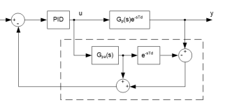
001SMITH structure.png
 

Attachments

  • 002Source code.txt
    1.6 KB · Views: 31
  • 003OB35_100ms_calls.pdf
    83.1 KB · Views: 35
I am looking forward to that example with a PID controller combined with the Smith predictor


Although it happens otherwise sometimes (me being one of the violators), the forum prefers the OP make at least an honest attempt to solve the problem themselves, then make comments for improvements and bug fixes.

You mentioned finding something in FB, but we do not even know what language you plan to use.
 
Thank you for your contribution!

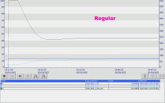
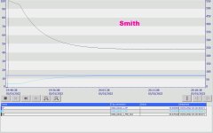
Please find attached the results. Conclusion: It is indeed effective. Especially with long delay times (like this 104 Sec.). The shorter the delay, the less effective the Smith method is.

It would be great if I could make a model based on the PV, SP & CO. Does anyone have experience with making models without step response in the PLC?

I program in all languages. Preferably in SCL.

Regular.jpg Smith.jpg
 
It would be great if I could make a model based on the PV, SP & CO. Does anyone have experience with making models without step response in the PLC?


It would indeed. STEP excitation in the open loop is the most preferable way, but there are other excitation signals as well. I don't know anything about your academics background, but you should know that in control theory systems are often compared based on its step responses even though step excitations are very rare in the real world. There are parameters that are defined in order to measure quality of response to a step input so we can compare the responses and in the end the performance of the applied control. Such parameters are settling time, rise time and max percentage overshoot.
It is possible to perform system identification in the closed loop even though there is a strong correlation between input and output data (output data are returned via feedback to the input signal) which can produce misleading results.


Anyway, this is not a forum for academics debates. I highly suggest you to consult the book "System Identification, Theory for the User", by prof Lennart Ljung, especially chapter 13 "Experiment design". I used this book a lot during my postgraduate studies, a long time ago, when I was young and ambitious.

Lennart Ljug SyS ID.jpg
 
Last edited:
The system must be "excited". A step jump is the easiest way to excite the system since the step jump is made up of many frequencies. In motion control a step jump is not preferred because it can damage equipment.
I have used swept sine waves and M and W profiles. These are much more difficult to implement.


The advantage of a step change is that it is relatively easy to determine the plant gain, dead time and time constant by inspection if the response is plotted. See the www.controlguru.com site.
 
@drbitboy
Swept sine waves aren not that difficult the way you implemented them. As the frequency goes up the velocity or rate of change goes up too. It is easy to exceed the limits of the rate of change. You also ignored the second derivative limitations. The output goes up with the frequency squared. The result is that the control output or CV will saturate at plus or minus 100% and make the data invalid.
Try again.

BTW, I use swept sine waves when modeling hydraulic valves.
 
Try again.


I expect there are many different profiles that fit the description "swept sine waves."


As the frequency goes up the velocity or rate of change goes up too ... The output goes up with the frequency squared.


Velocity of what? Output of what? Unless you are going to give me a proper spec, it is not worth it with 32-bit floats. That was interesting enough.
 
Last edited:
I expect there are many different profiles that fit the description "swept sine waves."
The amplitude of the swept sine wave must decrease and the frequency increases.

Velocity of what? Output of what? Unless you are going to give me a proper spec, it is not worth it with 32-bit floats. That was interesting enough.
Velocity if you are talking about motion, rate of change in the PV in a general case. As the rate of change increases the output from the derivative term will increase because the derivative term increases as the error between the rate of change of the SP' and the PV' increases. Eventually the control output will reach +/- 100%. When the control output saturates you can no longer use that data for calculating the model.

BTW, our motion controller used 32 bit REALS in the past. The swept sine wave problem required we use 64 bit LREALs.

Try again.
 
Try again.


OP wanted something, I assume load change, to control against, or to control with, instead of an open loop step change. I provided it. If you think it needs bells and whistles, feel free to implement your own. I don't have to prove I can move bits around.
 

Similar Topics

Hi all, The problem is to control the dry mass with a delay time system. I know Smith Predictor method can do it but how to implement it on ladder...
Replies
4
Views
3,777
Hi, I would like to assemble a simulator/practice booster pump system that uses PID to maintain steady water pressure under various outlet demands...
Replies
0
Views
86
Hello, I have a motor that we are sending a RPM Speed Output from 0-100% to the VFD. However, the Motor HP needs to be limited to 6000 HP and the...
Replies
3
Views
92
I have S7 1512C controler for controlling 48 PID temperature loop, the output is PWM. Please I need the best, most efficient way to write the...
Replies
13
Views
620
Hi all, I'm having trouble solving a problem I've been working on for several months, and thought you might like a stab at it. The machine runs...
Replies
22
Views
966
Back
Top Bottom