Dear Expert,
I'm in a problem where I need to run my G120 CU250S in speed control PID mode and in a torque mode. The switching is done by DI0and theAI0 is for actual dancer position feedback in PID mode. (0-10V 10V is dance at bottom and 0V is dancer at top) While running on PID speed control method my aim is to assign an internal pid setpoint where the dancer must stay at 5V position. Further regarding the torque mode I am giving the torque set point via AI1terminals (0-10V ) .
I have assigned the parameters using TIA and still I couldn't get my desired action. Below are some main parameters that I have used and kindly let me know where I made the wrong.
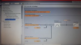
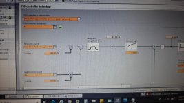
PID Parameters-
P2251 PID Controller is operated as = 0 /Technology controller is as main speed set point
P2200 PID Controller activation =r722.0 /via DI0
P2252 PID set point source =P2201[0] /Technology controller set point 1
P2264 actual value source = r755[0] / AI0 actual value in preset
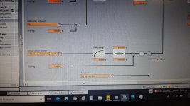
R2294 technology controller output = p1109 / total set point
R2224 technology controller fixed value effective = 40% i have made this via internal set point
Speed setpoints-
P1075 Supplementary set point = r755[1] / AI 1 actual value in present
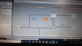
P1070 Main setpoint = I kept it 0 . (So far I understood from the portal view function diagram if the p2200 is true that the setpoint channel is deactivating and the controllers is working as a PID controller set point. But I'm not sure this point I am correct or wrong )
P1300 Control type = 20 / speed control encoder less
Torque setpoints-
P1511 Supplementary torque 1 = 0%
P1513 Supplementary torque 2 = 0%
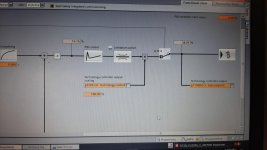
Also when i run the drive in PID Speed control mode the controller output is present till r62 : speed setpoint after the filter . but after that point there is no RPM value present since my motor is not running.
Can anyone help me identify what wrong I have made so my motor controller is not to rotate in PID mode ? In torque mode the motor is rotating according to the potentiometer equivalent that i have connected to AI1 terminals.
Here I have attached the portal screenshots for what i mention above in function block diagram way.


