PLC Analog Input Circuits

ImThomas

Member
Join Date
Feb 2024
Location
Perth
Posts
7
Hi all,
I’m an electrician with limited knowledge of PLC circuits.
Typically I will see simple 2/3/4 wire terminations for transmitters on electrical drawings where the 4-20ma signal goes through a resistor and then the PLC analog input.
Recently I have been getting drawings where the input circuit is more complicated involving multiple resistors and capacitors. My first impression was that it was converting the 4-20ma to a voltage but I just doesn’t make sense to me what the benefit of that would be.
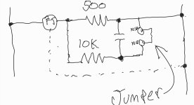
I have attached a couple of photos of the drawings of these circuits.
If someone could point me in the right direction of what I should be reading up on that would be great.
Cheers,
Thomas
 
Most normal 4-ma sensors inputs will have no resistors at all. I usually only see that if a sensor is putting out x-y volts and they are connecting it to a 4-20ma input, or visa-versa. But caps no, unless they are trying to filter out some noise.


FYI No pictures were attached.
 
Pull down Resistors are used when driving LED indicators. The drive current requirements of an LED is sometimes below the leakage current of an PLC output.
But Capacitors? I'd be interested to know what those are being used on.
 
Running a 4-20mA signal, or a 0-20mA one, though a precision resistor across the input terminals gives the input a voltage signal


20mA & 2.5 ohm = 50mV
20mA & 3 ohm = 60mV
20mA & 500 ohm = 10V (0-20=0-10V, 4-20=2-10V)


In reality the analog inputs that are mA are actually voltage inputs with the resistor inside.


The use of a capacitor on an analog signal I have never heard of and IMPO would alter the signal
 
2nd image looks like a low pass filter. Most modern PLCs have filtering capabilities either built into the input module or with logic. What type of PLC are these interfacing to?
 
I think the images will come through this time.
Hopefully this gives more clarity to the question.
Cheers

Since it's a 2 wire 4-20mA transmitter the only thing the resistor in photo 1 is going to do is make the transmitter push harder to put out the mA signal it wants.

As a 2 wire transmitter it will do whatever it can, without destroying itself, to put out the correct signal.
 
The capacitor is shorted out downstream of the sensor, it does nothing (unless the jumper is removed). With the jumper in, there is effectively just 476 ohms in series with the sensor. I don't know why. With the jumper removed, the capacitor isn't shorted but now it's out of the circuit so it (still) does nothing. Only difference with the jumper removed, now there is 500 ohms in series instead of 476. I don't know what is going on here. Makes no sense to me. There must be some 3rd option apart from (jumper or no jumper). Maybe a second (additional?) sensor can replace the jumper? That doesn't make any sense either. It's pretty bizarre actually, never seen similar.
 
This is a re-drawn equivalent circuit. The jumper between x1:66 and x1:67 either shorts across the capacitor or takes it (and the 10k resistor) out of the circuit.

Edit: never mind. That's not a jumper, it's an input. Weird way to draw it.

Screenshot_20240209-234212_Samsung Notes.jpg
 
There the bottom of the capacitor is not tied to 0V, it's floating.

In that drawing the lower resistor with the jumper in would still be in the circuit, just parallel and drawing down the 500 ohm to 480 ohms (using the online parallel resistance calculator. )
With the capacitor the 10K would stop having an effect once the capacitor charged full, so maybe that's some kind of damping.
 
Per your edit that it's the analog input, not a jumper, then that is exactly as per pic 2 above.

The signal always goes through the 10K resistor and the 500 ohm resistor takes it down to 480 while the capacitor is charging, then the 500 ohm is blocked by the full capacitor.

To me it's making it easier for the transmitter to reach the signal level at power up, then force it through the 10K (and working harder)
 

Similar Topics

Hi all, I want to catch min piks of an analog signal when digital signal is on(pls see the attached oscillogram). My hardware is 5069-L306ER CPU...
Replies
3
Views
999
Hello I have a analog input signal that is bouncing a bit. The PLC card is a 1769-IF8 I changed the input card filter setting from 60hz to 50hz...
Replies
14
Views
4,870
Dear all I am using delta AH530 RS- 2 cpu with devicenet communication and now I am getting problem while configuration of AH6xa-05 which is...
Replies
0
Views
1,040
Hello everyone I got problem during practical. I am using delta plc model:DVP20EX00R2. Problem is that when i give 7v dc supply through bridge...
Replies
4
Views
2,436
Hello everyone, I have a plc 5 input card receiving an input from a conductivity Transmitter where 0ma=0 uhms and 20ma= 20,000 uhms The raw min...
Replies
8
Views
3,631
Back
Top Bottom