PLC Analog Input Circuits

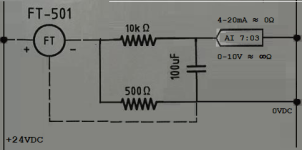
In building a control panel, there are few things I dislike more than having to wire individual components like those shown here. If they are necessary, the manufacturer of the device that requires them should have built them in.
A 2 AM patch, like adding a pull-up resistor to get a sinking proximity switch wired to a sinking PLC input, should only be in place until you can get your hands on the correct prox.
 
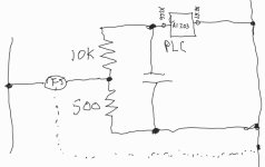
Ok here's rev2 of the simplified equivalent circuit, post-jumper/input epiphany.

I agree with the earlier suggestion of a low pass filter but I'm puzzled about the purpose of the 500ohm resistor. It seems to be forming a voltage divider (albeit implemented "backwards" from how a voltage divider is typically implemented), where the internal resistance of the analog input adds to the 10k resistor and the bulk of the current is shunted away from the input through the 500 ohm resistor.

Maybe previous revisions of this system utilized higher voltage inputs (ex:0-10V) and this new revision utilizes millivolt inputs, hence the divider?

Screenshot_20240210-065727_Samsung Notes.jpg
 
My first impression of the circuit was that the 4-20ma signal would pass through the 500ohm resistor and the analog input would read the voltage drop across the resistor with the 10k ohm resistor to reduce the current flowing through the analog input. But had no idea what the capacitor was for. Obviously I was not on the right path.
 
The chemical engineer's contribution (i.e. grain of salt):
IMG_5711.png
I see four possibilities: Sensor and Analog Input (AI) each use one of two modes: current (assume 4-20mA); voltage (assume 0-10V).

  • Sensor is 4-20mA; AI is 4-20mA
    • steady-state current to AI: < 5% of total current from Sensor
      • This makes no sense; entire 4-20mA range of sensor delivers well below 4mA lower limit of AI.
      • Perhaps 4-20mA assumption for sensor is wrong
        • anything at or above 84-420mA from sensor would yield 4-20mA at AI?
        • Or sensor could be 0-20mA, yielding approx. 0-1mA at AI.
          • At reduced resolution; why?
    • noise/transients: 10kΩ resistor + capacitor is first-order low-pass filter
      • time constant is 1s (τ = RC = 10kΩ × 100µF = 1)

  • Sensor is 4-20mA; AI is 0-10V
    • steady-state voltage at AI: 2V at 4mA; 10V at 20mA
      • Same at high side of resistors (i.e. steady-state)
    • noise/transients: 10kΩ resistor + capacitor is first-order low-pass filter

  • Sensor is 0-10V; AI is 0-10V
    • steady-state voltage at AI: 0V when Sensor@0V; 10V when Sensor@10V
    • noise/transients: 10kΩ resistor + capacitor is first-order low-pass filter
    • 500Ω resistor
      • limits current from sensor to 20mA
      • Provides slight additional resistance when capacitor is discharging
      • But it serves no real purpose
      • Removing it (and alternate path to 0VDS from sensor) would not change 10kΩ-100µF RC circuit at AI significantly
      • So why have it at all?

  • Sensor is 0-10V; AI is 4-20mA
    • steady-state current at AI: 0mA at 0V; 1mA at 10V
      • this makes no sense; entire 0-10V range of sensor delivers well below 4mA lower limit of AI.
    • noise-transients: 10kΩ resistor + capacitor is first-order low-pass filter
    • 500Ω resistor serves no purpose, I think
      • Removing it would not change steady-state current at AI
 
The chemical engineer's contribution (i.e. grain of salt):I see four possibilities: Sensor and Analog Input (AI) each use one of two modes: current (assume 4-20mA); voltage (assume 0-10V).

  • Sensor is 4-20mA; AI is 4-20mA
    • steady-state current to AI: < 5% of total current from Sensor
      • This makes no sense; entire 4-20mA range of sensor delivers well below 4mA lower limit of AI.
      • Perhaps 4-20mA assumption for sensor is wrong
        • anything at or above 84-420mA from sensor would yield 4-20mA at AI?
        • Or sensor could be 0-20mA, yielding approx. 0-1mA at AI.
          • At reduced resolution; why?
    • noise/transients: 10kΩ resistor + capacitor is first-order low-pass filter
      • time constant is 1s (τ = RC = 10kΩ × 100µF = 1)

  • Sensor is 4-20mA; AI is 0-10V
    • steady-state voltage at AI: 2V at 4mA; 10V at 20mA
      • Same at high side of resistors (i.e. steady-state)
    • noise/transients: 10kΩ resistor + capacitor is first-order low-pass filter

  • Sensor is 0-10V; AI is 0-10V
    • steady-state voltage at AI: 0V when Sensor@0V; 10V when Sensor@10V
    • noise/transients: 10kΩ resistor + capacitor is first-order low-pass filter
    • 500Ω resistor
      • limits current from sensor to 20mA
      • Provides slight additional resistance when capacitor is discharging
      • But it serves no real purpose
      • Removing it (and alternate path to 0VDS from sensor) would not change 10kΩ-100µF RC circuit at AI significantly
      • So why have it at all?

  • Sensor is 0-10V; AI is 4-20mA
    • steady-state current at AI: 0mA at 0V; 1mA at 10V
      • this makes no sense; entire 0-10V range of sensor delivers well below 4mA lower limit of AI.
    • noise-transients: 10kΩ resistor + capacitor is first-order low-pass filter
    • 500Ω resistor serves no purpose, I think
      • Removing it would not change steady-state current at AI

Excellent analysis. I think you've made it obvious that there's little chance of it being anything other than a 4-20 or 0-20mA sensor, going to a 0-10V input, with a low pass filter.

What are your thoughts on the first (one resistor) circuit? 220 ohms single resistor doesn't make much sense.
 
I'm not sure why there is concern, the field wiring is the dashed lines and the internal wiring(already completed...or it should be) is not of concern to those doing the field wiring(3 simple connection), it should just be ignored. If the circuit doesn't work and the 3 connections are correct, it is not the electricians problem.
 
I'm not sure why there is concern, the field wiring is the dashed lines and the internal wiring(already completed...or it should be) is not of concern to those doing the field wiring(3 simple connection), it should just be ignored. If the circuit doesn't work and the 3 connections are correct, it is not the electricians problem.

What about the OP made you think there was concern? He wants to understand.

God forbid a tradesman actually try to understand something. Just follow the instructions without question, you lowly drone!
 
I'm not sure why there is concern, the field wiring is the dashed lines and the internal wiring(already completed...or it should be) is not of concern to those doing the field wiring(3 simple connection), it should just be ignored. If the circuit doesn't work and the 3 connections are correct, it is not the electricians problem.

The question is purely for educational purposes.
 
  • Sensor is 4-20mA; AI is 0-10V
    • steady-state voltage at AI: 2V at 4mA; 10V at 20mA
      • Same at high side of resistors (i.e. steady-state)
    • noise/transients: 10kΩ resistor + capacitor is first-order low-pass filter
That's correct. The 500 ohms in series with the 4-20mA 2-wire transmitter creates a 0-10V voltage drop signal across the AI input.


The AI input, being a voltage input has relatively high impedance so inserting the low pass filter 10K resistor (+ 100uF cap) creates a negligible error, but has a fairly stiff low pass frequency.
 
An update for those who are interested.

After measuring the volt drop across the resistors and analog input I found that the analog input was reading a volt drop approximately 10% less than the volt drop across the 500ohm resistor.

Speaking with our switchboard manufacturer, he told me that the circuit is intended to reduce noise caused by the specific flow meter we are using. That is why they convert from 4-20mA to 2-10V. The reduced voltage at the analog input is compensated for in the program so that the reading remains accurate.

I also asked why he was using 220ohm resistors for the 4-20mA inputs. He told me the specific brand of PLC only has 40ohm internal resistance and the transmitters need around 250ohms to operate correctly.

Thanks for your help guys.

Thanks for the update. 40ohms input resistance on the old PLCs is surprising. What kind of PLCs were they? Typically a 4-20mA input is 250ohms, or at least it has been on all the ones I've measured, except for one weird Danfoss controller that was 500ohms.
 

Similar Topics

Hi all, I want to catch min piks of an analog signal when digital signal is on(pls see the attached oscillogram). My hardware is 5069-L306ER CPU...
Replies
3
Views
998
Hello I have a analog input signal that is bouncing a bit. The PLC card is a 1769-IF8 I changed the input card filter setting from 60hz to 50hz...
Replies
14
Views
4,865
Dear all I am using delta AH530 RS- 2 cpu with devicenet communication and now I am getting problem while configuration of AH6xa-05 which is...
Replies
0
Views
1,040
Hello everyone I got problem during practical. I am using delta plc model:DVP20EX00R2. Problem is that when i give 7v dc supply through bridge...
Replies
4
Views
2,436
Hello everyone, I have a plc 5 input card receiving an input from a conductivity Transmitter where 0ma=0 uhms and 20ma= 20,000 uhms The raw min...
Replies
8
Views
3,631
Back
Top Bottom