PLC Rookie Intern Help?

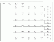
Roy, if you use my version, your Light 6 should look like the Output 3 (except with changed addresses) in the posted example using Latches and a One-Shot.

If you wish to make the rungs more complicated, you could use Rung 001 as a pattern for Lights 2 through 6 (leaving Light 1 similar to Rung 003). That adds a bunch more instructions but still only does the same job.
 
Last edited:
I followed this example on Latch and Unlatch by Lancie1 and it worked great. I am a little confused on how to continue this for the rest of my 3 lights. Explain please. Do I just start with light 6 and work my way back to 1? Do I put all this from 6-1 on Rung 001 and just extend the branch to make it fit. You guys are great.
 
Roy, Let me see if I can explain it so you can do it. I could do it for you, but that would not teach you much that you might need to know later.

You need 8 rungs, 000 to 007. TIP: Go ahead and add or insert new rungs after Rung 000, so that you have 8 rungs. The old END rung is the same. Add Outputs on these rungs according to the descriptions below.

Rung 000: This rung will be exactly identical to your old 3-Light version.

Rung 001: This rung is different than the other Outputs because it should ALWAYS be for the LAST, or highest Light Output. It will have the same number of instructions, the same B3:0/1 Pushbutton Pulse, and the same number and layout of 3 parallel output branches, except the addresses should be adjusted or changed to be for your new LAST Light Output (which will probably be O:2/5 or similar and the next-to-last O:2/4 or similar). Your Rung for Light 6 should look like the old Output 3 in my posted example (except with changed Output addresses).

Rung 002: Similar to old Rung 002, except now the Outputs on this rung are for O:2/4 (Latched) and O:2/3 (Unlatched).

Rung 003: Similar to old Rung 002, except now the Outputs on this rung are for O:2/3 (Latched) and O:2/2 (Unlatched). Do you see any patterns here from Rung 002 to Rung 005?

Rung 004: Similar to old Rung 002, except now the Outputs on this rung are for O:2/2 (Latched) and O:2/1 (Unlatched).

Rung 005: Similar to old Rung 002, except now the Outputs on this rung are for O:2/1 (Latched) and O:2/0 (Unlatched).

Rung 006: Similar to old Rung 003, has the same B3:0/1 Pushbutton Pulse, the same Latched Output O:2/0, and the same XIOs for O:2/0 through O:2/2, except now there are 3 additional XICx in series. Can you figure out what they should be?

Rung 007: The END statement, always the same but never to be forgotten. I once forgot to put in the END statement for an old Unitronics robot. It about tore up the shop before I could shut it down, but that is a story of another time.

That's all!
 
Last edited:
I didn't realize that rungs 14 thru 21 were missing in the pdf I posted in post #2. My pdf file writer only wrote one page per file. Here they are. Please accept my apologies.

Edit:
I merged the 2 files and attached the file with rungs 0 thru 21.
 
Last edited:
Thanks a bunch guys. I am gonna try again in the morning. I was told that a SQO is complicated for maintenace guy to troubleshoot. SO I need to do it with XIO, XIC, Latch Unlatch and OSR. This is above my head. My gut was to do the SQO cause it is the most simple. I need some experience iwth OTL and OTU. You guys are great.
 
I was told that a SQO is complicated for maintenace guy to troubleshoot.

Yes, SQO should ideally be used only when the sequence is too complex or when a large number of different sequences are required for the same outputs in different conditions/run modes.

Using a counter to solve this problem ensures easy troubleshooting for maintenance guys as well as minimum programming effort.
 
sorry: I0.1= PUSHBUTTON
M12.1= MEMORY BIT FOR ONESHOT (RISING EDGE)
Q4.1= LIGHT 1
Q4.2= LIGHT 2
Q4.3= LIGHT 3
Q4.4= LIGHT 4
Q4.5= LIGHT 5
Q4.6= LIGHT 6
(S) = LATCH
(R) = UNLATCH
I have it setup so that it will constantly scroll through lights 1 to 6 every time you press the push button but not if you hold it in.
 
Last edited:
Thank you very much Lancie. I have no experience with AB but hopefully it will convert and that he can see that it is conditions for setting/resetting each lamp.
 
Zane, it will convert, but not instruction-for-instruction or line-by-line. In many AB controllers, the One-shot instruction may only have one following output instruction (no input types or rung branches after the OSR One-Shot-Rising:

OSR [One Shot Rising]
Warning! Do not place input conditions after the OSR instruction in a rung when using a Fixed or SLC 5/01 controller. Unexpected operation may occur.

The SLC 5/02, 5/03, 5/04, 5/05 and MicroLogix controllers allow you to use one OSR instruction per output in a rung.
Rockwell Software

I will convert it and post a picture.
 
If you think they hate the SQO, you're really gonna get groans and moans from spaghetti latch logic.

I like sequencers when the inputs are sequenced and the application has a lot of I/O.

Your first example program could be done with a BSL (bit shift left).
 
Last edited:
Yes, but boss said to do it without SQO, without counter, without anything except one-shot and latches. What can one do except rebel and refuse the order?

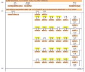
Here is Zane's program converted to use RSLogix. It has still has all the unnecessary instructions, and is not set up to make it easy for a beginner non-typist to copy and past rungs. One more conversion is needed....

Zane's 6-Light Sequencer.JPG
 
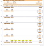
Now removing unnecessary instructions, and rearranging so the rungs can be easily copied, pasted, and edited...

6-LAMP SEQUENCE WITHOUT COUNTER-VER. 3.jpg
 
Last edited:
Thanks Lancie, the code i wrote did have a bit of excess to it, i did it to ensure that no two lights could be on at the same time. It is nice for you to show me the AB way of doing it and the second version trimmed down. I should have explained earlier to the OP about the rung order being necessary because of cyclic scanning (last instruction taking priority). As ever your advice is appreciated.
 

Similar Topics

Basic question, I'm having a hard time with terminology, "devise a circuit that will turn on a light to indicate that a momentary input signal...
Replies
42
Views
11,589
PLC not receiving voltage, display screen and i/o not lighting up. power supply receiving 115 volts ac. When you remove plc wire from power supply...
Replies
2
Views
2,160
I'm trying to integrate a Beckhoff IPC with a Controllogix PLC. There is some documentation, on the Beckhoff website, on how to do a PLC-PLC comms...
Replies
0
Views
46
kindly need to understand why can't upload the plc
Replies
2
Views
60
Hello all, I have a one problem. I would like to upgrade Mitsubishi PLC Q02 to Q03UDVCPU. I have Q02 program and I change to PLC type and try to...
Replies
3
Views
62
Back
Top Bottom