You are using an out of date browser. It may not display this or other websites correctly.
You should upgrade or use an alternative browser.
You should upgrade or use an alternative browser.
Problem with 1769-IF4 and wiring
- Thread starter matooz
- Start date
rta53
Lifetime Supporting Member
Does the processor have a program in it? Your initial question was in regards to the analog input not reading. Obviously it's not going to read as long as the processor is faulted. Have you tried clearing the fault?
Ken Roach
Lifetime Supporting Member + Moderator
Resolve the I/O module connection error first.
Confirm that you have a 1769-ECR correctly installed on the right side of the I/O bus.
Switch the 1769-IF4 module back to Internal power, and remove all wiring from it.
That should let your controller power up and run properly. If it doesn't then you probably have a damaged 1769-IF4 module.
It would be easier to run this circuit as a voltage input than a current input, since you probably just have an ordinary 24V bulk power supply, rather than a transmitter that is intended to give you a steady current loop.
Ken Roach
Lifetime Supporting Member + Moderator
If you connect this circuit as a current loop, you're looking at three resistances in series: 1000 ohms, 0-5000 ohms, and 250 ohms (inside the module).
Good old Ohm's Law says I=V/R
With the pot at full resistance, I = 24 volts / 6250 ohms = 0.00384 amperes.
With the pot at zero resistance, I = 24 volts / 1250 ohms = 0.0192 amperes.

Good old Ohm's Law says I=V/R
With the pot at full resistance, I = 24 volts / 6250 ohms = 0.00384 amperes.
With the pot at zero resistance, I = 24 volts / 1250 ohms = 0.0192 amperes.

Ken Roach
Lifetime Supporting Member + Moderator
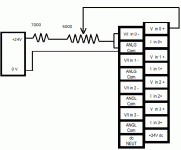
The way I would do this is to wire the potentiometer as a voltage divider.
Because your source is 24V DC, and you only want 0-10V DC for the analog input, you need to have 7000 ohms in series with the 5000 ohm potentiometer, instead of the 1000 ohms you have now.
If the fixed resistor is R1, with a value of 7000 ohms, and the potentiometer is R2, with a value of 0 to 5000 ohms, we can use the simplified voltage divider equation where the voltage drop is proportional to the ratio of the resistances:
V R2 = V total x ( R2 / RTotal)
With the resistor at full scale:
V R2 = 24 x (5000/12000) = 10 volts
With the resistor at half scale:
V R2 = 24 x (2500/12000) = 5 volts
With the resistor at zero scale:
V R2 = 24 x (0/12000) = 0 volts
This is a lot easier to measure, too, because you can just put a simple digital or analog voltmeter in parallel with the input terminals.

Ken Roach
Lifetime Supporting Member + Moderator
Oh, that was intentional.
Sometimes this Forum works like a hostile witness; the Poster will answer questions but will not volunteer information.
Eventually, matooz came through with useful information and I hope he got his analog input module working. I'm glad he did and I hope he becomes a regular Forum member.
But some of the recent threads that require twenty inquiries to get basic information out of a first-time poster have become pretty darn tiresome.
Oh, that was intentional.
Sometimes this Forum works like a hostile witness; the Poster will answer questions but will not volunteer information.
Eventually, matooz came through with useful information and I hope he got his analog input module working. I'm glad he did and I hope he becomes a regular Forum member.
But some of the recent threads that require twenty inquiries to get basic information out of a first-time poster have become pretty darn tiresome.
oh, in that case great reference!
Not only has this site been a good learning experience but also a lesson in humility. Thanks for the b--- busting. Will be glad to use this site again. Keep up the good work. Oh and by the way I will be bumping my voltage up to 25 to give me my 4-20.
Last edited:
elfmanp
Member
To rta53 - I am trying to understand A-B's wiring diagram. I get the fact that I have to supply power for the signal loop, but can I use the same power supply as what I am using for the module power or do I need to specify a completely different power supply.
Yes, but make sure you do not overload it.Can I use the same power supply as what I am using for the module power... ?
rta53
Lifetime Supporting Member
To rta53 - I am trying to understand A-B's wiring diagram. I get the fact that I have to supply power for the signal loop, but can I use the same power supply as what I am using for the module power or do I need to specify a completely different power supply.
As Lancie said it is fine to do this as long as your power supply is large enough.
Similar Topics
I'm trying to get an upload from a machine for backup purposes. The upload seems to work fine but at the end I get errors and no upload. It...
- Replies
- 2
- Views
- 1,403
Hi All~
I have a case (designed by my boss But he has left the company)
Please refer to the attached picture...
- Replies
- 6
- Views
- 2,399
Dear All members
I have problem about CPU CompactLogix 1769-L31 as follows;
Step 1. I connect this CPU 1769-L31 with 1769-PA2 and 1769-ECR...
- Replies
- 3
- Views
- 1,512
Hi Gents:
I met a problem with one of my 1769-OB32 module. Some of the channels suddenly malfunction -- The light indications for the channel are...
- Replies
- 1
- Views
- 1,602
I have a MICROLOGIX 1500 system which includes a HSC module. One of the counters is configured as a ring counter. When the counter overflow bit is...
- Replies
- 0
- Views
- 2,899


