JLand
Member
I have a question about process interlock naming. I want to hear opinions, as well as if there is a relevant standard.
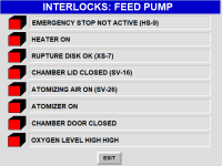
When naming specific conditions, for example a pump is interlocked on a discharge side pressure transmitter, do you describe the interlock on the HMI as the interlock in the okay state ("Discharge Pressure OK"), in the not okay state (Discharge Pressure High), or state-agnostic ("Discharge Pressure")? Or perhaps some other way? Keeping in mind, the text cannot by dynamically changed.
I can't make up my mind what I prefer. I see upsides and downsides to all three.
OK state can be confusing, because to the operator if they see an X next to "Discharge Pressure OK", they are being told two different things, that the discharge pressure is not OK (as notated by the X) but that pressure is okay (because of the description text).
Not-OK state can also be confusing, because it introduces a potential double negative interpretation of the state (an X by "Discharge Pressure Not OK" could mean that discharge pressure not OK is not the current state).
Lastly, a state-agnostic solution requires process knowledge, which all operators may not have. The operator would have to know that the pump requires a lower discharge pressure in order to operate.
I am mulling over this topic in the context of a PlantPAx installation. The interlock on a device that is not in the OK state is represented by a black and white "X" next to the description.
Thanks!!


