Rockwell help with MSG Instruction

arth608

Member
Join Date
Jul 2017
Location
Auburn Hills
Posts
7
Hello All,

This might be a simple question for most of you. I am working on performing some tests on an EIP device through RSLogix 5000.

Based on the information from the EDS files, I have created two user-defined data types that would allow me to use MSG instructions and pull data from those assemblies. Assembly 108 is read/write and Assembly 109 is read-only.

My question is in regards to Assembly 108. How to I write by passing the entire assembly through MSG instruction and Set Attribute Single service.

See the attached document for reference.
 
Is there any reason you aren't using the Generic Ethernet device in the I/O tree? That's usually what is done with assembly numbers.


If you must, assembly numbers are instance numbers in class 0x04. The assembly data is in attribute 0x03 of the instance.
 
Could you please post the EDS file?
I see your program and based on the data type for instance 108 of the assembly object, the program looks good. So I want to confirm the structure of the user data type corresponds to the description in the EDS.
 
Thanks for that detailed set of information !

The word document includes some screenshots and the detail that when he executes a MSG instruction to read Assembly Instance 108, he gets a "Configuration Data Size Too Large" error.

The problem is likely the odd number of INT sub-elements in your user-defined data type.

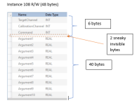
Assembly 108 consists of ten "Argument" REAL type elements, and three INT type elements (TargetChannel, CalibrationChannel, and Command).

That's just 46 bytes of data, but Studio 5000 reminds you that the UDT is 48 bytes in size. That's because ControlLogix will insert buffer data into a UDT to make the next data type start on a 32-bit boundary.

So when you select the Tag with the UDT data type as the source for the MSG instruction, the ControlLogix sends the whole 48 bytes, including the extra two bytes between the INTs and the REALs. The device rejects that because it knows Instance 108 is only 46 bytes long.

I don't think there's an elegant workaround, but I usually like crude and easy-to-understand methods anyhow.

I would move all the data from the UDT into a SINT[46] array, then use that as the source of the MSG instruction. You need one COP to move the integers (destination length 6 bytes) and one COP to move the floating-point values (destination length 40 bytes).

48_byte_UDT.PNG
 
Last edited:
Heh, check out my .sig below. Programming is mostly bookkeeping i.e. keeping things in their proper columns, while the initial approach here was writing numbers across the lines between columns.

Btw, doesn't this mean the read is not actually working either, i.e. it is not writing the last word (two bytes) of Assembly_108_Write.Argument10, and it is not writing the actual values from the E/IP device into their corresponding targets? However, since the initial values in the REAL .ArgumentNs are all 0.0, which is all 0 bits, and the values coming from the external E/IP device are also 0.0, it isn't apparent in the visible results. So the SINT[46] array and the two COPs is needed for both reads to and writes from Assembly_108_Write.

Assuming the Logix is LSByte-first,

  • try putting the value 16,777,216.0,
    • which has its lower 16 (actually 23 or more) bits of all 0s,
  • into Assembly_108_Write.Argument10 before the read,
  • and I suspect it will not change after the read.
BETTER YET
  • put the value 16,777,218.0
    • which has its LSBit as a 1, and the next 22 (at least) are all 0s
  • into Assembly_108_Write.Argument10 before the read,
  • and I suspect it will change to 16,777,216.0 after the read.
 
Ken,

Thank you so much for the detailed explanation. I am happy to say that your suggestion worked with COP function. Would it be safe to say that if our production center changed the assembly to have 4 INT values (making it even) that we would NOT run into this issue? and that would change the assembly on the device to 48 bytes as well and logix would not add these two buffer bytes?
 
Reply

Ken,

Thank you so much for the detailed explanation. I am happy to say that your suggestion worked with COP function. Would it be safe to say that if our production center changed the assembly to have 4 INT values (making it even) that we would NOT run into this issue? and that would change the assembly on the device to 48 bytes as well and logix would not add these two buffer bytes?

Yes assuming the 4 INTs are contiguous. If you have control of the assembly, inserting a "future/spare/unused" INT would not raise any eyebrows.
 

Similar Topics

Hi!! I'm looking for Temperature rise calculation software from Rockwell, I just download "Product selection toolbox 2022" but this software is...
Replies
1
Views
217
Hello, I am trying the AOI provided by Rockwell to read Modbus TCP, the version is 2.04 The connection looks good to the modbus server. I...
Replies
4
Views
654
Hi everyone, I'm working on a project that involves using a Keyence LR-X100 sensor in Studio 5000 V35 ladder logic to determine the object's...
Replies
4
Views
679
Machine has existing DN devices that are connected to SLC 5/04. All communication is working fine now. Supplier wants to remove some DN devices...
Replies
6
Views
844
Hey I am trying to used the ISATR8800002_2015 from machine builder library, and when I try to use the HMI i get the error cannot interpret area...
Replies
1
Views
699
Back
Top Bottom