RSlogix - Industrial Control Simulator

Looking at the Method 2 routine again, I don't think I did Rung 0010 correctly. There has to be a way to select the NEXT part, out of all the possible parts between IP3 and IP4. What I have only on Rung 0010 will only look at the B3:1 value of the LAST part that went past IP4. It wil take some more and different logic.

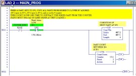
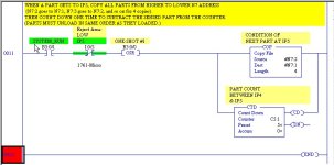
What has to be done On Rung 0010, change the Source for the EQU instruction from "#N7:0" to "N7:1", which was the good/bad value for the FIRST part to pass IP4. Then on Rung 0011, after any bad part has been rejected, you have to copy all Good/Bad numbers up by 1 position, in this order:

Copy N7:2 to N7:1 (replacing the old N7:1 which was just handled).
Copy N7:3 to N7:2
Copy N7:4 to N7:3
Copy N7:5 to N7:4, doing copys up to the value of C5:1.ACC ("5" in this case)

This will insure that the next part to arrive at IP5 will haves its B3:1 condition stored at N7:1.

Once the copying is completed, only then do you trigger the CTD and decrement C5:1 by 1, so C5:1.ACC always shows the number of parts outstanding between IP4 and IP5.

There is an easy way to do the copying using Indexed Addressing, but my atrophied brain has shut down for today. Maybe someone else can take over here and finish this little routine. As an alternative, you could simply use the FIFO method!
 
Last edited:
I think this R3 version should fix the problem with the Indexed Addressing method. See the changes in Rungs 0010 and 0011. I don't guarantee that my work here is error-free.
 
Last edited:
When the ones marked LOW were not seeing anything (no object in front of the switch), the indicator was ON, which I think means that the sensor (digital not analog) output contact was CLOSED (allowing the built-in indicator light to turn ON). When these same sensors were tripped by a part, the light would go OFF, I think indicating that the sensor output was then LOW or OFF or OPEN or a binary "0".

Yes I saw that too. The light only goes ON when the part isn't triggering the kicker for the ring.

Then you can use the FFL to insert new objects as they occur, which advances the FIFO position indicator for each object. When you get rid of an object (rejected in this case), you trigger the FFU, which pushes the data for that object to the FFU Destination address.

OK that was the part that was missing : the purpose of FFL and FFU.

To use the Indexed Addressing method, you load an "offset" (a number to be added to a base address) to memory location S:24. Then when you use an Indexed adddress designation (put a "#" in front of an address, RSLogix automatically adds the value of S:24 to that address. In this way, you can in effect have a variable address that changes as needed for the process.

WOW that's very convienent. This is the reason why I didn't understand the relationship between the two MOV logic box at rung #0009, because I had to AssUME that S:24 is an index and that putting a # sign before a destination automatically refers to that S:24 index. Just to clarify... (I might be wrong, I frequently am) There can be only one index using this method? Because a # can only refer to one index (S:24) in any RSLogix program?

[...]we save the part condition (0 = good, 1 = reject, but you could use any numbers from 0 to 32767) to the B3:1 memory word by using Indexed Addressing and the Counter Accumulator value as the index value. This may be how the authors wanted you to do this task, since they did mention "index" in their description.

I do not understand the relationship between B3:1 (as a source??) and the two others that I think already understand which are S:24 and #N7:0.

As Forest Gump said, "That is all I have to say about that right now".

A'ight Forest! Thank you for the chocolate! No kidding, you're a genius Lancie... 🤞🏻
 
What has to be done On Rung 0010, change the Source for the EQU instruction from "#N7:0" to "N7:1", which was the good/bad value for the FIRST part to pass IP4.

Thank you Lancie. Can you explain me the difference between #N7:0" and "N7:1" ?

Much appreciated,
Cheers.
 
There can be only one index using this method? Because a # can only refer to one index (S:24) in any RSLogix program?
No, you can use more than 1 index, but each time you use it, in the rung above, you must reset the value of S:24 to the correct index at that time, because it will be changed by the next index version.
I do not understand the relationship between B3:1 (as a source??) and the two others that I think already understand which are S:24 and #N7:0.
B3:1/0 was your original Good/Bad bit indicator. In the FIFO version, I had to change that to word B3:1 becasue a FIFO manipulates words, not bits. To be consistent, I left the word version B3:1 indicator in the Method 2 Indexed Addressing version.

The key things are: To track infomation contained in a part, as the part moves from location to location, you need to know two things: the identity of the part, and the bit of information about the part. C5:1.ACC = identity of the part, and B3:1 = information about the part.

C5:1.ACC is used as the index to move the value in B3:1 to a word memory storage address, starting with the first word after N7:0, which is N7:1. The first part seen will cause the counter to count to "1", and the "1" will be saved in S:24, updated for each new part that arrives when no part has yet left the conveyor at IP5. I think N7:1 always has to be the Indexed Address of the part that arrives at IP5 (because of the COP on Rung 0011), so I could eliminate using the Indexed Address for that occasion, and use simply N7:1 instead of #N7:0. It is safer to use the N7:1, because then I don't have to worry about the S:24 index getting changed as the part moves from IP4 to IP5.

Note that the use of the indexed addresses in the COP instruction on Rung 0011 will change the value of S:24. (The COP used with indexed addresses creates its own value in S;24 for each copy, and the number of copies is set by the Length parameter). So S:24 must be reset by the MOV in the Rung 0009 top output branch, before it can be used again in the bottom branch.

Mitureg's Industrial Control Simulator 7D- Rung 0011.JPG
 
Last edited:
The key things are: To track infomation contained in a part, as the part moves from location to location, you need to know two things: the identity of the part, and the bit of information about the part. C5:1.ACC = identity of the part, and B3:1 = information about the part.

Thank you Lancie. I will have to think more about your information in post #20. There is lot of new things. I'll get back on that post when I'll have it done. I need to write all descriptions rung-by-rung in a separate document as an assignement.

Cheers
 
This is where the rubber meets the road. To know which instruction to use for IP8 (XIC as shown or XIO as you propose), you have to know HOW the IP8 sensor operates. Does the sensor "go LOW" when it see something, as indicated by the label right in your instructions, or does it "go HIGH" and OPENS a contact when it sees something? I AssUMed that it goes LOW or opens when it sees a part. In other words, it is a Normally Closed (N.C.) sensor as traditionaly defined. I think only YOU can tell because you have the Simulator program and I don't.

To make a NC sensor open, you have to trigger it with a part. Therefore, if you are looking at a NC physical sensor that is now OPEN, but you want your PLC instruction for that sensor to go closed (or HIGH) when the sensor opens (goes LOW), then you must use a XIO (think of the "O" as the "Opposite" of your physical switch).
 
XIO & XIC Truth Table
Physical
Input XIO XIC
1 0 1
0 1 O

Memory tricks:
For XIO: What you "see" on the input is Opposite of you get out inside the PLC.

For XIC: What you "C" on the input is what you get out inside the PLC.

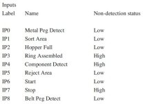
Hi Lancie, I am reviewing this post and I get confused because you corrected a mistake in regards to the non-detection status of the input IP8 (belt peg detect). According to the documentation, this input has a non-detection status marked as LOW. Doesn't it mean that it goes HIGH or CLOSES when it sees a part? Therefore it would be a Normally Open Contact instead of a N.C ?

I have rephrased your post, tell me if I am on the right track.

Added to this problem was the fact that the non-detection status of the physical input relay switch or sensor had to be considered. For example, to know which PLC instruction to use for IP8 (XIC or XIO), we have to know HOW the IP8 sensor operates.

from lancie1 reviewed by mitureg said:
Does the sensor "go LOW" when it see something or does it "go HIGH" and CLOSES a contact when it sees something? We assume that it goes HIGH or CLOSES when it sees a part as indicated in the instruction package (non-detection status: LOW). In other words, it is a Normally OPENED Contact (N.O) sensor as traditionally defined.

To make a N.O sensor CLOSE, we have to trigger it with a part. Therefore, if we are looking at a N.O physical sensor that is now CLOSED, but we want our PLC instruction for that sensor to go OPENED (or LOW) when the sensor CLOSED (goes HIGH), then we must use a XIO (think of the "O" as the "Opposite" of your physical switch).

Keeping that in mind, would there be input contact relays (N.C or N.O) that have been mixed up in the shuffle considering this table?

Capture_Non-DetectChart.JPG
 
Last edited:
I think you are correct. In the original table, the labels were jammed together so that I did not notice that "non-detction status". Was that there all the time? I did not see it (which is not surprising as I am nearly blind in my left eye and only 20/40 in the right). If so, then that would mean that the Lows should be Normally Open contacts that go High and send out a 1 when they detect a part.

That would make sense, because the IP7 Stop is a High which would then be Normally Closed as it should be for a stop pushbutton. That is the condition of the input device, not the output of the PLC instruction that looks at that device. For the Highs such as the Stop button, you have to use the opposite of Closed, or XIC to get a 1 when the device is not activated.

Which all means that the indicator lights for sensors IP0 and IP1 in the video are ON when the sensor outputs are LOW or OFF. That is sort of strange, because most that I have seen with a built-in indicator light, turn the light on when the sensor is triggered, not when it is in the non-detect state. (The only sensor I have seen that turn the indicator light OFF when they are triggered are the ones with a NC or HIGH output)! There is nothing that says that your simulator version does not have some of the inputs reversed from the equipment shown in the video.

If the table is really true, then my assumption below about the video was not correct, and the indicator lights work opposite of typical units.
When the ones marked LOW were not seeing anything (no object in front of the switch), the indicator was ON, which I think means that the sensor (digital not analog) output contact was CLOSED (allowing the built-in indicator light to turn ON).

If the LOW means normally open in the non-detect state, then your program needs a lot of changes!
 
Last edited:
There is nothing that says that your simulator version does not have some of the inputs reversed from the equipment shown in the video.

The video I presented was the closest I could find for this problem. It was not provided with the documentation package I received and is just a third party piece of information that might differ from the actual student documentation.

If the LOW means normally open in the non-detect state, then your program needs a lot of changes!

OK I will review all input and make it as an exercise to clarify this twilight-zone-bizzaro-world-equal-and-opposite communication with the inside-out PLC world.

In popular culture, largely influenced by the Seinfeld television program, "Bizarro World" has come to mean a situation or setting which is weirdly inverted or opposite of expectations.
 
OK the only changes needed for the non-detection status needed to run the program would be for the input:

Ring Assembled (IP3)
Component Detect (IP4)

For IP3, there are the 2 PLC command XIO and XIC at rung 0007 so I didn't touch them, I seem to be lucky for that one...

However, I have made the modification for IP4 at rung 0008-0009 and edited the comment:

!!!! Component Detect input device has a non-detection status of HIGH, meaning it will go LOW to return a "1" Therefore a XIC has to be used (or a N.C PLC contact relay) !!!!

But now, the output of rung 0008-0009 won't behave as it should since the PLC command is set to the opposite to serve the Component Detect input device attributes.

How do we reconciliation that? Do we need to modify the preset for the CTU and the two MOV at rungs 8 and 9 ?

Much appreciated,
Cheers
 
I felt guilty and embarassed for messing up the program due to not seeing that note about "non-detect", so I just finished going through and changing all the inputs that needed changing based on our current understanding of LOW and HIGH. I added notes explaining each.
For IP3, there are the 2 PLC command XIO and XIC at rung 0007 so I didn't touch them, I seem to be lucky for that one...
I think all 3 of the inputs on Rung 0007 should be swapped to the opposite state to make it work correctly (which I did in the version below). Whether you need an XIC or XIO on any rung depends on 2 factors: whether the pysical sensor is NO (HIGH) or NC (LOW), and whether you need a TRUE or FALSE from the PLC instrcution for that rung logic. Sometimes you need a TRUE to turn on an output, sometimes you need a FALSE to verfiy that something is OFF or has not happened before you turn on an output. On rung 0007, we need to first verify that a metal part was DETECTED, and also whether a ring was detected at the same time. If it was, put a "0" in our flag B3:1 for a correctly-assembled part, or if not, then put in a "1" for a bad part.

But now, the output of rung 0008-0009 won't behave as it should since the PLC command is set to the opposite to serve the Component Detect input device attributes.
That is why rung 0007 has to be modified, and also rungs 0010 and 0011.

How do we reconciliation that? Do we need to modify the preset for the CTU and the two MOV at rungs 8 and 9 ?
I think if the input XIC's and XIO's are corrected, the CTU and MOV logic will be okay as is. Only the COP on rung 0011 actually needs the OSR (CTD will only count down one time anyway), and for some of the early SLC PLCs, a OSR has to be right next to a single output.
Place the OSR on the rung immediately before the output instruction...

Warning! Do not place input conditions after the OSR instruction in a rung when using a Fixed or SLC 5/01 controller. Unexpected operation may occur.
Rockwell Software
 
Last edited:
One other thing is the Ring Chute Jam Alarm mentioned in the instructions. I did not know exactly how to handle that. I put an instruction in Rung 0002 to shut off everything if it triggers. The problem is that we don't know what sensor triggers that alarm. Apparently in the simulator, that is built-in and not part of the ladder program.
 

Similar Topics

Hi everyone, I've got a strange problem. We have a machine that custom mixes chemicals and is controlled by a AB industrial PC talking to a AB...
Replies
7
Views
9,770
Hi Everyone, I am not proficient in RSLogix 500 so I have a question regarding the evaluation of N7:0 data as an input. So as I understand in...
Replies
1
Views
88
Hi folks, in the alarm manager of Rslogix 5000, the tag-based alarm has been created. But when I tried to change the condition, it was found the...
Replies
2
Views
158
I have a little bit of experience with Allen-Bradley. I have a Micrologix 1500 (RSLogix 500) and a PanelView Plus 7 (FactoryTalk View Studio ME)...
Replies
3
Views
179
Back
Top Bottom