RSlogix - Industrial Control Simulator

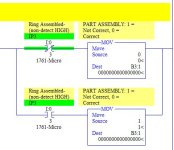
On rung 0007, we need to first verify that a metal part was DETECTED, and also whether a ring was detected at the same time. If it was, put a "0" in our flag B3:1 for a correctly-assembled part, or if not, then put in a "1" for a bad part.

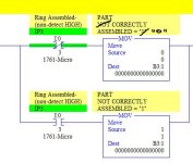
Is there a workaround to correctly identify each logic box descriptions at rung 0007? Each time I edit one the other one follows. I figure it's because they both use the same B3:1.

One other thing is the Ring Chute Jam Alarm mentioned in the instructions. I did not know exactly how to handle that. I put an instruction in Rung 0002 to shut off everything if it triggers. The problem is that we don't know what sensor triggers that alarm. Apparently in the simulator, that is built-in and not part of the ladder program.

I think it's just an extra. At this point the program for what it is has enough supportive content to demonstrate understanding of the simulator in my opinion. This problem is for the Distinction grade understandably.

Cheers.
Industrial_Control_Simulator_0007_MOV.JPG
 
Is there a workaround to correctly identify each logic box descriptions at rung 0007? Each time I edit one the other one follows. I figure it's because they both use the same B3:1.
Just like any other address comment, of course it is associated with the address. This description goes with the address B3:1. You can word it any way you want. I chose to word it based on what is needed to take action, identifying the bad parts for ejection. Since the good parts need no action at the reject point, then it is not as important to know that they will be equal to 0. (If you don't like the definition, you can easily swap so that 0 = not correct and 1 = correct).

If you want to include both the 0 and 1 states, your B3:1 address description would have to say something like this: "PART ASSEMBLY: 1 = Not Correct, 0 = Correct". By the same thinking, then your Pushbutton and switch comments should also say "1 = ON, 0 = OFF" (or for Stop pushbuttons, 1=OFF, 0=ON) because they have 2 states also.

The important thing is to at least identify what one of those states means. Then the other state (0 or 1) by default means the opposite or inverse. This is a common beginner misperception - that you can identify the state of the moment (not very well, because it can change from 0 to 1 or 1 to 0 at any time).
 
Last edited:
If you want to include both the 0 and 1 states, your B3:1 address description would have to say something like this: "PART ASSEMBLY: 1 = Not Correct, 0 = Correct". By the same thinking, then your Pushbutton and switch comments should also say "1 = ON, 0 = OFF" (or for Stop pushbuttons, 1=OFF, 0=ON) because they have 2 states also.

Go it. Cheers

Industrial_Control_Simulator_0007_MOV2.JPG
 
Hi Lancie, on post #20 I think there's a word missing. It's a bit of information I need. Could you tell me what the word is?

so I could eliminate (eliminate wut?) using the Indexed Address for that occasion, and use simply N7:1 instead of #N7:0. It is safer to use the N7:1, because then I don't have to worry about the S:24 index getting changed as the part moves from IP4 to IP5.

Cheers
 
Maybe this translation would be clearer:

"Then I could choose NOT to use the Indexed Address (#N7:0) for that occasion, and simply use the FIRST-USED word in the Indexed address range from N7:0 to N7:4. N7:1 is always the first-used word that gets set, because when the FIRST part is detected, the Counter Accumulator goes from 0 to 1, and it is the "1" that gets moved to the NEXT S:24 index (which will always be N7:1 for the 1st part detected). Then on the last rung, the old FIRST part gets rejected and the COP causes Part #2 on the belt to move up from N7:2 to the old FIRST Part index (N7:1).

It is safer to use the N7:1 "first-part position", because then I don't have to use the S:24 index at IP5, and also worry about the S:24 index getting changed as the part moves from IP4 to IP5."
 
Last edited:
I am glad you asked that question. That got me to looking at the last part of the program, specially Rung 0011. It occurred to me that there was a bad error. The COPY needs to have a variable length that depends on the value of the C5:1 Accumulator. Since COP Length cannot be a variable, I had to split the COP out into 4 rung branches, for C5:1.ACC = 2, 3, 4, and 5 (assuming that there can never be more than 5 parts between IP4 and IP5).

If there is actually only 1 part in that section of the belt, then we do not need to do the COP at all, so we don't have to look at the case for C5:1.ACC = 1, because that part just got rejected anyway. Here is how the revised Rung 0011 should look (see attached PDF file).

If you had used the FIFO method, then the Counter and the COP would not be needed, because the FFL and FFU keeps up with the Position pointer automatically.
 
Last edited:
Is there a workaround to correctly identify each logic box descriptions at rung 0007?
Here is a little tip about your Comments. You can insert "Enters" or the Line Feed Return to choose where your comment lines are wrapped to the next line. See how I did your comment for B3:1 by picking where to wrap the line.

Mitureg's Rung 0007 Comment Tip.JPG
 
Last edited:
The COPY needs to have a variable length that depends on the value of the C5:1 Accumulator.

It's slooowly making more sense to me this whole Indexed Addressing logic. The FIFO way was easier to understand I think... and I'm glad you choose the more advanced way to achieves our means as an exercise.

I Did the mod...

Cheers.
 
I don't know if I would call the indexed addressing more advanced than using a FFL and FFU instruction. I would call it a more involved or more complicated method, but at the same time easier to follow and maybe easier to troubleshoot for an electrician. The more functions that an instruction (such as the FIFO instructions) can do internally, the harder it is to understand exactly how it works and what it is doing.

Those two FIFO instructions on two rungs could replace Rungs 8, 9, 11, and part of 10. It is good that you have learned about indexed addressing, but it is not used very much in newer software and PLCs that have Indirect Addressing.
 
Last edited:
Maybe this translation would be clearer:

"Then I could choose NOT to use the Indexed Address (#N7:0) for that occasion, and simply use the FIRST-USED word in the Indexed address range from N7:0 to N7:4. N7:1 is always the first-used word that gets set, because when the FIRST part is detected, the Counter Accumulator goes from 0 to 1, and it is the "1" that gets moved to the NEXT S:24 index (which will always be N7:1 for the 1st part detected). Then on the last rung, the old FIRST part gets rejected and the COP causes Part #2 on the belt to move up from N7:2 to the old FIRST Part index (N7:1).

It is safer to use the N7:1 "first-part position", because then I don't have to use the S:24 index at IP5, and also worry about the S:24 index getting changed as the part moves from IP4 to IP5."

Got it. Cheers.
 
Those two instructions on two rungs could replace Rungs 8, 9, 11, and part of 10. It is good that you have learned about indexed addressing, but it is not used very much in newer software and PLCs that have Indirect Addressing.

Could we roll back to the FIFO version? I am having a really hard time trying to figure out how Indexed Addressing works, probably because you've adapted it to RSLogix limitations.

Cheers.
 
Last edited:
Sure, just copy Rungs 8 through 10 from the program in Post #10 (7D-R1)and replace Rungs 8 through 11. It will be easy if you open two copies of RSLogix, and load each program, the copy from the old and paste into the new. You will need to change the inputs to match our current definition of LOW and HIGH.
 
Last edited:
OK Got it. Replaced rung 8 to 10. Deleted 11. Verified the non-detect status associated with hardware. I dragged and drop using 2 RSlogix application opened. I had notification of address collision, I just pressed "LEAVE' all the way and did "Verify Project", so far so good...

Is everything normal on your end for this version?

Cheers.
 

Similar Topics

Hi everyone, I've got a strange problem. We have a machine that custom mixes chemicals and is controlled by a AB industrial PC talking to a AB...
Replies
7
Views
9,771
Hi Everyone, I am not proficient in RSLogix 500 so I have a question regarding the evaluation of N7:0 data as an input. So as I understand in...
Replies
1
Views
88
Hi folks, in the alarm manager of Rslogix 5000, the tag-based alarm has been created. But when I tried to change the condition, it was found the...
Replies
2
Views
158
I have a little bit of experience with Allen-Bradley. I have a Micrologix 1500 (RSLogix 500) and a PanelView Plus 7 (FactoryTalk View Studio ME)...
Replies
3
Views
180
Back
Top Bottom