RSlogix - Packing Line

mitureg

Member
Join Date
May 2013
Location
Canada
Posts
199
Hello Everyone, thank you for taking the time to read this post. I got this short program of a Packing Line. I documented everything. I was hoping someone could have a look and point out mistakes and simplified logic advice?

Here is the description:

The packing line carries boxes of different sizes that need to be separated at the end of the first conveyor. Which direction the boxes travel at the end of the first conveyor should be decided by using the input sensors IP1 and IP2. If the box is a short one, the inputs will only be energised one at a time. If the box is a long one then, for a short period, both inputs will energise at the same time.

When the box reaches the end of the first conveyor, which is driven by OP0, it will come to rest on the circular plate and will energise the sensor IP3 (the first conveyor will also stop). The plate will then turn either to the left or the right depending on the length of the box. OP2 turns the plate to the right; OP1 turns the plate to the left.

Once the plate has turned, the box will be pushed on to the next conveyor by either piston OP4 or OP3. Output OP6 drives the left-hand conveyor and output OP5 drives the vertical conveyor. Inputs IP4 and IP5 are sensors which detect the boxes on the conveyors as they are transported to the correct loading areas depending on their length.Once the boxes pass these sensors there should be a short delay and the respective conveyor should stop.

Write a program to carry out the previously described operation and, as with the previous assignments, use the documentation facilities. When the program is complete, test its operation using the simulation package. To use the graphic simulation click on a box which, will place the selected box on to the first conveyor then operate the start switch IP0.

Program in attachment.

Much Appreciated,
Cheers! :site:
Packing_Line_5_1.jpg
 

Attachments

  • PACKING_LINE_5 - Copy.zip
    16 KB · Views: 14
it appears that you are experienced in mainly relay logic.
consider writing a program using a step sequence
this could help you in both this problem and the previous post

Write a sequence map first
eg.
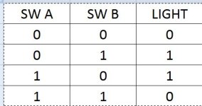
(two way light cct)
A = off and B = off then light = Off
A = on and B = ON then Light = Off
A = off and B = on then Light = on
A = on and B = Off then Light = on

 
Last edited:
The plate will then turn either to the left or the right depending on the length of the box. OP2 turns the plate to the right; OP1 turns the plate to the left.
Alex, that description sounds familar. I believe this student problem has been presented, discussed, and solved on this site before. Search and you may find it.

Site "Advanced Search" possibilities: "packing line" with 4 replies 6 months ago or longer, "converyor packing line", "conveyor pusher plate", and so on.
 
Last edited:
These previous threads should be applicable:

http://www.plctalk.net/qanda/showthread.php?t=43021&highlight=long+short+boxes&page=4

http://www.plctalk.net/qanda/showthread.php?t=32318&highlight=%22long+short+boxes%22

http://www.plctalk.net/qanda/showthread.php?t=72736&highlight="box+pusher"

http://www.plctalk.net/qanda/showthread.php?t=16611&highlight="box+pusher"

http://www.plctalk.net/qanda/showthread.php?t=11484&highlight="long+short+boxes"

http://www.plctalk.net/qanda/showthread.php?t=15993&highlight="pusher+plate"

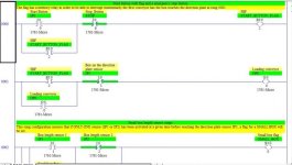
Rung 002: This rung configuration assures that if ONLY ONE sensor (IP1 or IP2) has been activated at a given time before reaching the direction plate sensor IP3, a flag for a SMALL BOX will be set.
I don't think your logic for detecting a small box will work. For example, a large box moving toward Sensor IP1 will first turn ON IP1 while IP2 is still OFF. With your Rung 002, your Small Box Flag B3:0/0 will go ON, even though the box is LARGE.

What you have to do is figure out all combinations of IP1 and IP2 as Ian showed you in Post #3.
T4:5 = 2 seconds, starting when IP1 = ON and sealed in with T4:5/TT.
If T4:5/DN is ON, IP1 is ON, and IP2 is also ON, then Box = LONG.
If T4:5/DN is ON, IP1 is ON, and IP2 is OFF, then Box = SHORT.
 
| Timer 1st Sensor 2nd Sensor LONG |
| T4:5/DN IP1 IP2 B3:0/0 |
|----| |--------| |-----+------| |-------------(L)----|
| | |
| | 2nd Sensor SHORT |
| | IP2 B3:0/1 |
| +------|/|-------------(L)----|

 
Last edited:
Hi Lancie, what is the purpose of the Timer at the beginning of the rung you've put in post #5 ? Why is there a latch on the B3 and where do they unlatch? As of now, using this solution I get both flag at the same time.

I will do more test..

Cheers.
Alex
 
Hi Lancie, what is the purpose of the Timer at the beginning of the rung you've put in post #5? To determine the time range, within which you take a snapshot of the state of the two input sensors. Without a time range, you have no way to know the relative positions of a box. Has a small box just triggered IP1? Has a large box triggered IP1 but not yet reached IP1? Time is all you have to determing how far the box is from the first sensor. Even with a timer, you will still have to run some trials on the actual system to determine what Preset to set in your timer.
Why is there a latch on the B3 and where do they unlatch?
The latch is to make the snapshot at the exact time that T4:0 = 2 seconds.
If the box is a long one then, for a short period, both inputs will energise at the same time.
That timer Preset value needs to be adjusted by YOU (the only person here that has access to the actual equipment) so that the timer goes done when a long box hits the second sensor, but still is triggering the first sensor. The time can be off a few tenths of seconds but should still work.

The Unlatch would be done right after the box reaches IP3, and you determine which way to kick it. Then you immediately Unlatch B3/0 and B3/1. I leave the details for the student's education!
As of now, using this solution I get both flags at the same time.
My idea was to always look at both bits at a certain time - the time when a large box would be triggering both sensors. At that time only, you can set either the long or short box flag. At any other time, you cannot determine the meaning of the sensors, because you don't know where the box is relative to each sensor. I think there may be an error in my logic, so that it will work for the long (with correct timer setting) but not the short. I will check that using LogixPro and get back to you.

Remember that you are dealing with a moving box, so your IP1 and IP2 will have to go on and off at the correct times to make a simulation work correctly. You cannot simulate these sensors with manual switches very well and get the proper results every time.
 
Last edited:
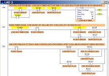
Here is a revised method to detect the Long and Short boxes.
Picture 1: Timer T4:0 has timed to 4 seconds, DN bit is ON.
Picture 2: T4:0/DN ON, IP2 ON, and IP1 ON = Long Box
Pictue 3: T4:0/DN ON, IP2 ON, and IP1 OFF = Short Box.

I would use Step Relays (B3 bits set up to indicate where the box is in the process, and to track and control WHEN each step is done). Otherwise, you are depending on your B3:0/0 and B3:0/1 Length Flags to still be ON, even after the box has left the first conveyor. In your case, your Small Box Flag will drop out when the next box triggers one or both of the sensors. Any box downstream of IP3 will then not be handled correctly. Remember, you must design this system as if there will be a stream of boxes (real system), not just one at a time (student imagination).

Mitureg's Packing Line- S1 Timer Done.JPG Mitureg's Packing Line- S2 Long.JPG Mitureg's Packing Line- S3 Short.JPG
 
Last edited:
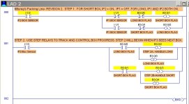
After more testing, the attached method works okay, provided that for Short Boxes, IP2 is located downstream far enough so that IP1 always goes OFF before IP2 goes ON (as specifed in the instructions below). Remember that restriction, if you test this with a simulator and manually-operated switches in place of the box sensors.
If the box is a short one, the inputs will only be energised one at a time. If the box is a long one then, for a short period, both inputs will energize at the same time.

Mitureg's Packing Line- R2 Short.JPG
 
Last edited:
The key that made that last method work is when a long box is found, the Short Box Flag is locked OUT.

Locking out or interlocking the Short has to be done because:

(1) There are only 2 types of box in this system, Long and Short;

(2) If a Long has been detected before a Short (which it will be), then the Short Flag must be locked out because a Long will look like a Short once the Long gets past IP1;

(3) A Short can still be detected because it will not be locked out UNLESS a long has first triggered BOTH sensors at the same time.

(4) It is not really necessary to also lock out the Long when a Short is detected.

There have been several methods used to solve this old student problem. Here is another way using a RTO timer to measure the width of each box or package. All this type of student solution depends on the conveyor always traveling at a constant speed. If the conveyor has a variable speed drive, then a better method must be used, such as a bar-code scanner or other method of positive ID.

http://www.plctalk.net/qanda/showthread.php?t=78659
_
 
Last edited:
Hi Lancie, thank you for your post during the weekend. Sorry I was away last weekend. I followed your new instructions. I tested the one with the timer too, but like you said the revision is better and less complicated. Plus it's an hypothetical problem for students so we don't have access to the actual hardware to calibrate everything according to the size of the box and the distance between the sensors. I'm following you on that.

Could I have your opinion on the second part of the program? It's the part that deals with the vertical and left hand conveyor.

The following is a list of the inputs and outputs, in addition to this list use any of the Flags, Timers, and Counters that you require in your program.

IP0 Start button
IP1/2 Box length sensors
IP3 Box on the direction plate
IP4 Box on the vertical sensor
IP5 Box on the left conveyor

OP0 Loading conveyor
OP1 Turns direction plate to the left
OP2 Turns direction plate to the sensor right
OP3 Push the box on to the vertical conveyor
OP4 Push the box on to the left sensor conveyor
OP5 Vertical conveyor
OP6 Left hand conveyor


Cheers.
Here is my latest version in attachment.
 
Last edited:
Here are a few suggestions. I would add a SYSTEM RUN relay for safety, so that you can use it to disable all outputs when STOP is pushed. A RUN relay saves from having to put the Start & Stop buttons on every Output rung.
 
I made the modification for the SYSTEM_RUN safety. Does everything looks good besides that?
You still have the instruction for your STOP button backwards. I suggest that you do some tests using a real Normally Closed Stop pushbutton. Connect the Stop Pushbutton to a PLC input, then see what instruction you need to return a "1" or ON inside a PLC rung without the STOP being pressed. You may be surprised to find that it is NOT a XIO (not this ---|/|---) but this instead :(---| |---). That was a surprise for me too, about 50 years ago. That little conundrum catches a lot of students when they least expect it, on a homework problem or during an exam.

Physical STOP pushbuttons (not the PLC instruction for the Stop button) need to be Normally Closed for fail-safe purposes, so that a broken wire will do the same as opening the button and stopping the machinery. If you tried to use a Normally Open physical Stop Pushbutton, then a broken or disconnected wire would leave you with no easy way to stop the machine.

Must you use those TOF timers when TONS will work better for the purpose? TOFs can be confusing, and are rarely used except when necessary.
 
Last edited:
You may be surprised to find that it is NOT a XIO (not this ---|/|---) but this instead ---| |---). That was a surprise for me too, about 50 years ago.

YES OF COURSE, it's a STOP button. Not an usual relay contact. I understand now why this STOP button must be a XIC ---| |---.

Does that mean I have to force it in order to have my simulation on a PLC software working normally? Is there anyway to represent properly a N/O STOP button in RSlogix (I hope I am not getting confused with terminology here... sorry if I am).

OK I just realized that I didn't make the proper modification according to your last revision. Here it is now. I have changed the TOF for TON, you are right, it's much simpler like that.

Cheers.
 

Similar Topics

Greetings, I need to move various bits from a tag TO_SEND (type = SINT[20]) to a consecutive order into bits 0-15 of a tag = SEND (type =...
Replies
6
Views
4,569
Hi Everyone, I am not proficient in RSLogix 500 so I have a question regarding the evaluation of N7:0 data as an input. So as I understand in...
Replies
1
Views
87
Hi folks, in the alarm manager of Rslogix 5000, the tag-based alarm has been created. But when I tried to change the condition, it was found the...
Replies
2
Views
156
I have a little bit of experience with Allen-Bradley. I have a Micrologix 1500 (RSLogix 500) and a PanelView Plus 7 (FactoryTalk View Studio ME)...
Replies
3
Views
168
Back
Top Bottom