RTD to PLC

You have a 4-20mA sensor and you wired it up like it is a RTD sensor.


edit: you changed your schematics. This is better. So, do you have a passive or active transmitter? And how did you connect it, 2-wire or 4 wire?

may i know how do you know how is the transmitter is passive or active?
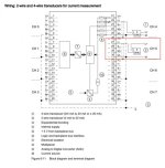
im using 2-wire. so the wiring is as per the red box in the picture.

correct me if im wrong.

Screenshot_2015-12-02-02-19-57.jpg
 
I am also a little confused as to what kind of sensor you are using.

i am using 3 wired RTD sensor. and the 3 wire is connected to a transmitter to get the reading of 4 - 20mA.

edit: output from the transmitter is 2 wire. that is why im choose two wire connection to analog input module.
 
If I understand you right, you connected it ok. Are you sure the transmitter is working ok?
 
If I understand you right, you connected it ok. Are you sure the transmitter is working ok?

i calibrated the transmitter with dry heat box. and tested okay.

edit - Should i change the AI module? i change it for a few time already. the result are still the same
 
Last edited:
The switch must be in position C not position D. In position D the card is powering the sensor (the card is active).
I'm sure this is the problem. In my first post, I asked you to read the manual and change the switch to pos. C.

C: 2 wires passive analog input module
D: 4 wires analog input module, but you should also use this position if you have a 2 wires sensor but the module powers the loop (not your case).

i had fix the problem. in the Ladder Program.

IW 298 should be write as PIW 298. i dont know how or why. Because in the Analog input module in TIA is shown as IW 298.

The same goes to Analog Output in program.

thank you guys for replying here. :)

scale 1.PNG
 
i had fix the problem. in the Ladder Program.

IW 298 should be write as PIW 298. i dont know how or why. Because in the Analog input module in TIA is shown as IW 298.

The same goes to Analog Output in program.

thank you guys for replying here. :)

You mentioned you were using an S7300 AI card, so I'm assuming you are using an S7300 CPU as well.

The 300's have a concept called the "Process Image", where it at the beginning of the PLC scan, it grabs a certain amount of the IO table, and buffers it into memory. This is called the Process Image. The amount of memory it grabs is configurable, but the default is often 256 bytes. Analog values are, by default, placed outside the Process Image, but could be moved inside it if you want to. One of the advantages of this buffering is that the Process Image will not change during the scan of the PLC. This is called a synchronous scan, and is what users expect from pretty much all PLCs (except the Logix family, which is asynchronous).

When the PLC started the scan, it probably copied IW0-IW254 into the Process Image (PI) table. When you use the command IW298, it looks at the buffered PI, saw that there was no value stored there, and returned 0. When you use the command PIW298 (or, in portal, IW298:p), it goes directly to the communications interface and grabs the most recent value from the IO card. This is called a peripheral read.

I'm not 100% sure why these PLCs only buffer part of the IO data. My guess is that, historically, copying the IO memory took a lot of time, and the PLC should only copy exactly as much as needed to avoid wasting time. In the newer Siemens PLCs (S71200/1500), the entire IO table is buffered in the process image, and so this isn't an issue. You can still use the :p to command a periphery read/write, to intentionally grab the most recent value instead of the buffered value.
wow, what you just said is totally make sense to me. thanks for your explanation.

just wondering if the memory size of the s7 memory card played a big part in the scanning.
 
wow, what you just said is totally make sense to me. thanks for your explanation.

just wondering if the memory size of the s7 memory card played a big part in the scanning.

The memory card (MMC) used in the S7 300 is used for load memory. Think of the MMC as the hard drive of your PC. When the 300 CPU powers on, it takes the program and data in load memory and copies it into Work Memory (RAM, essentially). IO memory is a separate entity. Both work memory and IO memory are limited by the CPU you've selected (bigger CPU = more work and IO memory), whereas load memory is based soley on the size of the MMC in the CPU.

As a rule of thumb, if you don't know how big an MMC you need, select an MMC the same size or bigger than the work memory of your PLC.

nice info. thanks :D
 

Similar Topics

How do you program a Micrologic 1200 RTD module using a Micrologic 1400 PLC? I'm using RSLogix Micro to program the ladder logic. I've wired the...
Replies
4
Views
2,850
I'm an aspiring instrumentation engineer. I need to connect following to the PLC Micrologix 1100 RTD "PT100" the input module is AI 0-10v can I...
Replies
6
Views
3,494
Hi, We have RTDs connected to a Siemens PLC S7-315 system. Out of the 15 or so RTDs connected, all show correctly except for 5. For all these 5...
Replies
2
Views
1,899
I am trying to use the Siemens S7-300 PLC system to monitor temperature changes using a two wire 100ohm platnium RTD. I am using a SM331 AI...
Replies
2
Views
13,655
Good Morning , I have a RTD , that I would like to wire into a 1756-IF8 Analog Input Card. Would you all a simple wiring diagram , of what...
Replies
4
Views
1,207
Back
Top Bottom