Siemens CPU 315-2DP Troubleshooting

Mullet

Member
Join Date
Jan 2024
Location
Colorado
Posts
20
I'll preface this by saying this is the first time I've worked on a Siemens system and I'm fairly unfamiliar with them. I might mess up some of the terminology or misunderstand some things. We have a guy who works on Siemens stuff but nothing as old as this and doesn't seem to have super in-depth knowledge to lean on.

Got called out to investigate an issue with a PLC. It's been installed since 2008 and supposedly working fine this whole time. They shut it down over the winter (seems to be a common thing they've done) and when they brought it back online it started throwing all kinds of faults and codes.

They have 6 tanks that they're controlling from it with various valves and sensors tied in. Each tank is linked in series with IM 151 modules.

The controller is showing an SF and BF fault light. The first tank in the series' IM 151 is all green lights and they have good values back to the readout at the control panel. Everything from tank 2 to 6 have SF/BF faults on the comm modules and the power and RTD modules. Voltage looks good. Electrician re-ran the Profibus cable from Tank 1 to Tank 2 and still didn't rectify the issue. Electrician also swapped out the entire rack of modules in Tank 2 and nothing.

Was able to poke around a little bit in the program but we don't have the Step 7 license so I couldn't access anything too deep. Most of the fault codes relate to OB122 (looks like a block of programming in the 315).
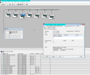
I/O access error, reading
P area, word access, Acess address: 272
Requested OB: I/O access error OB (OB122)
Priority Class: 1
External error
Incoming event
2/19/2024 15:39:07.310
(Coding: 16# 29 42 01 7A 00 20 01 10 00 00 00 00 24 02 19 15 39 07 31 02)

I was using an old computer that had TIA 15 on it and took a bunch of screenshots and some diagnostics files I saved I'd like to reference here but I'm transferring files from that laptop and can't get to them quite yet. Hoping somebody here might have some clues to point us in the right direction. I'll try to get the other information together for you guys here soon if that helps.

Thanks!
 
Does this IM151 have a bunch of dip switches on the front, and if so did the person who replaced it set them the same as the one they took out?
1708442173120.png
 
Sounds like a profibus or IM issue. What happens if you engage the terminating resistor at tank2? Was the IM151 replaced at tank2, if so was the address set correctly?
Back in the day, most folks, used address 1 as the CPU, 2 reserved for laptop or pc, 3 for first remote rack, 4 for the next etc..
Some folks reserved 2 & 3, and started remotes at 4. When the address is changed, you must cycle power to apply the new address, the switches are only read at start up.
 
Does this IM151 have a bunch of dip switches on the front, and if so did the person who replaced it set them the same as the one they took out?
View attachment 68172

Not sure we're gathering software and combing through information before we go back out yet but I'll make sure to take a look when we get there.

/e Sorry I read and replied too fast. Yeah he set the addresses back to what they were based on the drawings. Unsure about the extra dip switch which I didn't know about until I started reading around.

Sounds like a profibus or IM issue. What happens if you engage the terminating resistor at tank2? Was the IM151 replaced at tank2, if so was the address set correctly?
Back in the day, most folks, used address 1 as the CPU, 2 reserved for laptop or pc, 3 for first remote rack, 4 for the next etc..
Some folks reserved 2 & 3, and started remotes at 4. When the address is changed, you must cycle power to apply the new address, the switches are only read at start up.

Sorry I'm pretty unfamiliar with Siemens. What/where is the terminating resistor?

The IM151 was replaced and he set the address to what they have in the drawings. Looks like each tank is addressed in increments of 10. So 10, 20, 30, 40, 50, 60.

Everything has been power cycled at least once throughout this process. I was having trouble seeing the CPU at all until we did a power cycle and then I was able to poke around. I'm not super familiar with Siemens software so I'm not even sure I was getting into it correctly. I also don't have the Step 7 License so we weren't able to see the programming itself.
 
Profibus requires a termination resistor at the end of the daisy chain. By setting the resistor at Tank 2, you remove the rest of the chain. If tank starts working, then you know the problem is further down stream.
 
Profibus requires a termination resistor at the end of the daisy chain. By setting the resistor at Tank 2, you remove the rest of the chain. If tank starts working, then you know the problem is further down stream.

Is that what the Off/On switches near the dip switches for the addressing are? If so I believe those are set correctly but I think we spent most of our time looking at 1 and 2 since we saw 1 was good but nothing past it was.

We were focusing on 2. Could it be possible that 3, 4, 5, or 6 could be messed up and somehow it's still able to catch 1 but not the rest? We were approaching it from "Lets get 2 going and work up from there" but could we be missing something by doing it that way?

I talked to Siemens tech support. We were using TIA 15 to peek into the system but he said we needed STEP 7 so we're waiting on approval from Siemens to download that. We weren't able to look into the configuration of those modules because of the software which kind of limits our ability to troubleshoot in case the electrician put in a bad module or something like that. They also pointed out there needs to be a terminating cap of some kind on the bus and maybe the electrician also left that out when he swapped stuff out.
 
If the master has the BF (bus failure) lamp solid red then it is possible that some of the DP field devices have good communication (i.e. no BF) and for sure at least one will be in BF condition. Normally the nodes farther from the master will be more sensitive to problems like bad termination. If all nodes after one particular node are BF, it could be that such node in spite of not being the last node of the bus has the terminator switch on and should be in the OFF position.
If problem persist Simatic 7 may not be able to help and you will need and analyzer tool such as Softing's BC-700 or Procentec's Profitrace.
 
The problem may be at node 1 despite that it is green light.
Check the termination at node 1.
Replace the connector at node 1.

Tell us more about the entire system.
Bus speed ?
Distances ?
A sketch of the cable topology ?
 
If the master has the BF (bus failure) lamp solid red then it is possible that some of the DP field devices have good communication (i.e. no BF) and for sure at least one will be in BF condition. Normally the nodes farther from the master will be more sensitive to problems like bad termination. If all nodes after one particular node are BF, it could be that such node in spite of not being the last node of the bus has the terminator switch on and should be in the OFF position.
If problem persist Simatic 7 may not be able to help and you will need and analyzer tool such as Softing's BC-700 or Procentec's Profitrace.

I looked through all the panels and they're all set to OFF except the last one as expected.

The problem may be at node 1 despite that it is green light.
Check the termination at node 1.
Replace the connector at node 1.

Tell us more about the entire system.
Bus speed ?
Distances ?
A sketch of the cable topology ?

Good point. Might need to look closer at node 1.

Bus speed... not... sure honestly...

Distances... I'd say overall length from beginning to end... maybe 50 yards? Also this system has been running with minimal issues (So I'm told) since 2008.

I finally got the correct software from Siemens yesterday and managed to get in and poke around a bit.

I noticed one of the errors says mismatch but I did go through the module faceplates in the rack to what's configured and it all looks same-same.

Here's some screenshots and information that might help you guys understand. I really appreciate your insights and help. If there's anything I'm missing or can provide let me know.

I was gonna ask about the asset ID. Is that a randomly generated number or does that need to be based on something? Since he swapped out modules and things I was wondering if those need to be configured or anything.
 

Attachments

  • 2024-02-20_164911.png
    2024-02-20_164911.png
    398 KB · Views: 19
  • 2024-02-20_170803.png
    2024-02-20_170803.png
    308.9 KB · Views: 19
  • Diagnose2.txt
    3.3 KB · Views: 4
  • HW Config Network Diagnostics Overview.pdf
    204.2 KB · Views: 3
  • 2024-02-20_171914.jpg
    2024-02-20_171914.jpg
    366.9 KB · Views: 19
You can try for test. Take IM151-3 module from other non working cabinet to first cabinet Connect profibus cable and power to this other IM151-3 module (don't forget end resistor of IM151-3) Dont't change any slave dips and don't connect any IO-cards to IM-module.
If CPU detects this other IM151 module, but says faulty (as there is no configured IO cards connected) then problem is on cabling (or in first cabinets profibus connector outlet) after first working cabinet.
If it still says that for IM151-3 no available then there is other error.
Great advice! Gonna give this a shot.
 
Sidenote. As 6ES7151-1AA04-0AB0 is standard module, only one missing IO-module is permitted. If more than one is missing same time, the station will fail and not going to run mode. Pretty sure that IM-module is still regonized by CPU even if there is missing modules.
(lastly have tested this with ET200SP profinet IM HF (high feature) and for that this testing worked)
 
'module mismatch' is Siemens lingo for that there is a configured module, and when it cannot see it, then that counts as a 'mismatch'.
I suspect a problem with the connectors (they can degrade over time), or damage to the cable between the 1st and 2nd stations.
Other problems that can appear out of nowhere ..
. defect on the IM of the 1st or 2nd stations.
. a source of EMC that has been introduced.
. earthing has been changed or degraded
. equipotential bonding has been changed or degraded.
 

Similar Topics

Hi We were having a few power cuts and the CPU would not work. I had to reset the memory and he CPU would read from the memory card and start...
Replies
13
Views
3,163
Hi, Can anyone explain the difference between rebooting a Siemens CPU 315-2 PN/DP, either by setting the switch into stop and back into run...
Replies
5
Views
2,684
I have a Siemens S7 300 CPU 315-2 PN/DP PLC and CP 342-5. IM Module is configured via ethernet port. I have two profibus network. One on CPU and...
Replies
3
Views
4,137
Hi All. I'm creating several diagnostic screens for the maintenance personnel, displaying the I/O status. Do you know if it's possible to get...
Replies
4
Views
3,707
Hi i Have an OP7 [6AV36071JC200AX1] and a CPU s7-315 DP [6ES73152AF020AB0] I'm communicating between the two via DP, i need to set up the CPU so...
Replies
3
Views
1,403
Back
Top Bottom