Slow PID Loops

If I make my PID rung go true every x seconds, I also have to change the "loop update time" parameter in my PID setup to match that interval?

yes - that is the way it is supposed to be done ...

going further ...

if the long delays that you've mentioned are even remotely correct, then making the PID execute more frequently is probably NOT going to help improve the control ...
 
Sorry, that wasn't clear.. I meant increase the time of the interval, thus decreasing the frequency of execution.
 
Hey guys, thanks for all the responses!

Yes, the conveyor runs at a constant speed. There is a rotary feeder that controls the amount of product per unit time (I guess you could call that density) that is fed onto the conveyor and eventually into the mill. The speed of this feeder is the control variable in the PID loop.
That is part of the problem. That is a long dead time.

The 30 minute time refers to the amount of time the mill can take to get to the proper level. For example, say the pressure is 12 inches of water and the desired setpoint is changed from 12 to 15. To accomplish this change in manual operation, they would normally increase the feed rate (say from 25% to 40%). Then once the desired level of 15 is reached, the speed must be decreased again.
You have a manual feed forward system. This can be automated by ramping up the set point and that the rate of change of the set point is multiplied by a feed forward that adds extra material. When at the final set point the rate of change is 0 so no extra material is added.

I would have a feed forward based in the set point AND the rate of change in the set point. I would experiment with using a FIFO to put the current set point in and delay the set point by 3 minutes. I would then use the delayed set point as the set point to the PID. Hopefully the feed forwards do most of the work and get very close and the PID just closes a little bit of error that is left.
 
Use feed forwards

J E said:
Hey guys, thanks for all the responses!

Yes, the conveyor runs at a constant speed. There is a rotary feeder that controls the amount of product per unit time (I guess you could call that density) that is fed onto the conveyor and eventually into the mill. The speed of this feeder is the control variable in the PID loop.
That is part of the problem. That is a long dead time.

The 30 minute time refers to the amount of time the mill can take to get to the proper level. For example, say the pressure is 12 inches of water and the desired setpoint is changed from 12 to 15. To accomplish this change in manual operation, they would normally increase the feed rate (say from 25% to 40%). Then once the desired level of 15 is reached, the speed must be decreased again.
You have a manual feed forward system. This can be automated by ramping up the set point and that the rate of change of the set point is multiplied by a feed forward that adds extra material. When at the final set point the rate of change is 0 so no extra material is added.

I would have a feed forward based in the set point AND the rate of change in the set point. I would experiment with using a FIFO to put the current set point in and delay the set point by 3 minutes. I would then use the delayed set point as the set point to the PID. Hopefully the feed forwards do most of the work and get very close and the PID just closes a little bit of error that is left.
 
If all else fails, there is always Expertune. Not cheap, but it works great for tuning difficult PID loops and takes all the quess work out of tuning.
 
If all else fails, there is always Expertune. Not cheap, but it works great for tuning difficult PID loops and takes all the quess work out of tuning.
If the system could be tuned with a just a PID then fine. It is obvious from the statement above about the operators 'adding feed forward' manually so simple PID does not work well.

I am curious, how expert is expertune. Will expertune suggest using ramps and feed forwards and provide feed forward gains too?

[RANT]
A variable speed conveyor would have made control much easier.
Insert rant about the designers having no clue as to how this system was going to be controlled. You have all heard the rant before.
[/RANT]
 
Is it true that a PID in an SLC (e.g. 5/04) will automatically synchronize based on the LUT, and can therefore be on a rung without conditions?
 
I would suggest starting with a loop update time twice as long as the data update time. Also, start with conservative Gain and Integral Values, and no Derivative.
Following up on Peter's advice, if you see a setpoint change, or can predict a disturbance to the process, you can react faster to it by using Feed Forward. On the Logix this is accomplished by putting a number in the BIAS Term. Also as Peter suggested, controlling the rate of both the Feed and Conveyor System could speed up the response.

QUOTE FROM INSTRUCTION REFERENCE:

You can feedforward a disturbance from the system by feeding the .BIAS value
into the PID instruction’s feedforward/bias value.
The feedforward value represents a disturbance fed into the PID instruction
before the disturbance has a chance to change the process variable.
Feedforward is often used to control processes with a transportation lag. For
example, a feedforward value representing “cold water poured into a warm
mix” could boost the output value faster than waiting for the process variable
to change as a result of the mixing.
A bias value is typically used when no integral control is used. In this case, the bias value can be adjusted to maintain the output in the range required to keep the PV near the setpoint


END QUOTE:

You can find the manual here;

http://literature.rockwellautomation.com/idc/groups/literature/documents/rm/1756-rm003_-en-p.pdf

PID Loops with long dead times are a pain to tune, and require time and patience.

Stu.....
 
naegely:

Yes, that is correct. In the SLC500 PLCs, you put the PID in an unconditional rung.
However, the PLC5, and Logix 5000 PIDs need to be triggered at the same rate as the Update Time of the PID Loop.

Stu.....
 
Thanks Stu,

That's what I thought. I wonder why that wouldn't be the case in RSL5000, seems like a step backwards.

Rob
 
In order to use conveyor speed to control material infeed you need a mechanical or additional control system that guarantees that the conveyor is uniformly loaded with a constant density of material per lineal unit of conveyor length. Basically the length of the conveyor between the feeder and the mill would always be 'fully loaded'. Alternatively you need to measure the actual density as it enters the mill. If that were the case the distance between the feed and the mill wouldn't matter. I think J E is WAY too far along to ever get that.

As Peter said this is a deadtime issue. I would be interested to see if Peter's idea about delaying the setpoint will do the trick. I'm guessing you run with a relatively constant setpoint so it may not make much difference. What you really need to do is match your PID corrections to the effect on the system. This gets into the use of tools like Smith Predictors and other model-based control schemes. Simply speaking you fool your PID into thinking that it's control effort has an immediate effect by replacing the actual feedback with a value based on the correction and a model. The true feedback value is used to correct the feedback used by the PID when valid numbers are available. It's more complicate than just that but that is the idea. As you can see, deadtime sucks.

Feed forward would certainly be helpful but you should also be using feed forward's closely related cousin, disturbance rejection, if you can. In this case the disturbance is whatever is pulling material out of the mill. If you have any way of getting that information it will make your life alot easier. It is the single biggest determining factor in your infeed rate.

A final note on feed forward. Your system is an integrating system. The level (which is your setpoint) is the integral of the infeed rate (discounting disturbance) since the outflow from the mill is not an inherent physical quality of the mill. So, as Peter said, the rate of change of the level setpoint is what you really need for your feed forward. So if you use feed forward, make sure the setpoint is ramped at a rate that the infeed is capable of achieving assuming no outfeed.

Finally, don't expect more than what the system is capable of. You can only do so much. You are a slave to the physical construction of the system. For example, you may have a stable system where the infeed rate matches the outflow rate. With your present system if the outflow rate decreases you WILL get a level increase since you have no control over the amount of material already on the conveyor (total mass) or the speed that the conveyor is carrying that material to the mill (mass rate). If you could control conveyor speed you would have a better shot. But if that were the case you would need a different control method on your rotary feeder that tries to maintan a fixed mass per length value on the conveyor. But that could probably be a simmple system tied to conveyor speed.

Keith
 
from naegely:

Is it true that a PID in an SLC (e.g. 5/04) will automatically synchronize based on the LUT, and can therefore be on a rung without conditions?

maybe yes ... maybe no ...

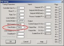
be sure that you fully understand how the "Time Mode" setting works before you jump into the pool ...

basic idea: if set for "TIMED" then the operation will be as you mentioned ... specifically, the "Loop Update" setting uses the PID's internal clock/timer to automatically "trigger" the PID into execution ...

but ...

if set for "STI" then the PID's internal clock/timer is NOT used - and the PID will execute/calculate each and every time that its rung is executed by the processor ... in this arrangement the PID should be placed in a Selectable Timed Interrupt file - whose "Period" should be set to match the PID's Loop Update setting ...

in BOTH cases, the PID rung in an SLC/MicroLogix system should always be UNconditional (no XIC, no XIO, etc.) ... AND - an external "trigger timer" will never be used ...

note that STI is the "default - fresh out of the box" setting - and these issues are some of the first things that we check when troubleshooting a PID in an SLC/MicroLogix system ... quite often they are set up wrong ...

PS ... if you have other questions along these lines, it would probably be best to start a new topic and discuss them there ... there is already a lot going on in this present thread and we really shouldn't distract the focus by bringing extra platforms into the mix ...
timemode.JPG
 
Last edited:
I just wanted to give an update on this situation. I was pulled off of this project before I could fully explore all of the options. I talked with the engineer who is still involved. He said that the loop was never tuned to satisfaction. The feed will be controlled manually. The loop can be used for short periods of time if the operators need to get away, but it doesn't hold setpoints in the log term.

Thanks for all the help. I learned a good bit about these loops even though I didn't get a chance to solve the problem.
 
FREE PID tuning tips pocket guide

We have offered a no charge PID tuning tip pocket guide for the past 5 years. Register to receive a copy at the controlsoftinc.com web-site. This will provide the basic outline on how to tune process control PID loops.

We have offered our INTUNE PID tuning software for 18 years, but this is not a requisite to getting the no charge PID tuning tips pocket guide.
 

Similar Topics

Hi all, I'm working on a wastewater plant with oxidation ditch aerators. The aerators are on VFDs and the operators want the dissolved oxygen in...
Replies
45
Views
17,686
Hello, I have a issue with tuning a slow acting PID loop using AB PIDE instruction. The system is designed to cool a tank after it heats up...
Replies
141
Views
102,892
Hello all, I have set up a PID loop which works fine except it is a bit slow during the startup. I wish that it would reach near the setpoint...
Replies
1
Views
1,835
Hi friends I have a L24ER-QBFC1B in a Level Control that you can see in the picture. Tank1 is the process tank. Level sensor is the process...
Replies
4
Views
3,060
Hey guys, I have a Controllogix and I am tying to control a PID loop for Chlorine (CL2). The trouble is the mixing point is 15 minutes away from...
Replies
16
Views
6,770
Back
Top Bottom