Studio 5000 integer to Real with 0 digit replacement

jbradtke9112

Supporting Member
Join Date
Oct 2018
Location
New York
Posts
8
Good morning all,

I'm integerating a device with a Rockwell PLC with V34 Studio 5000. The device reports error codes using a single integer to represent a decimal Error code.

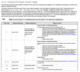
For example 201 means error code 2.1 I have existing code that works by converting DINT to String, then FIND the "0" digit, then INSERT the "." at the first found location of the "0", then delete the "0" digit, then convert STRING To REAL (see screenshot for code).

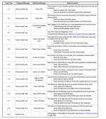
This works for most error codes except the device can report a 1.1 error code and a 10.XX error code (see screenshot). I don't believe my code will work as it will replace the 10 with 1.

Any alternative suggestions for the conversion? Am I missing something in my interpretation of the manual?

Thanks for any and all help!

Code Example.png Device Error Code Table.png Device Error Table 2.png
 
Last edited:
Based on your description of how the code is reported ('.' replaced by a 0) and the error tables, it seems like only the 10.xx errors will have their third character be a 0. So after converting to String you could check the third position character and if it's a 0 replace it with '.', and if it's not a 0 then run it through your existing logic.
 
Based on your description of how the code is reported ('.' replaced by a 0) and the error tables, it seems like only the 10.xx errors will have their third character be a 0. So after converting to String you could check the third position character and if it's a 0 replace it with '.', and if it's not a 0 then run it through your existing logic.

Ahh I like that. I was going down a different route which made it way more complicated. I'm going to give that a shot.

Thank you!!
 
My other thought was that if the 'xx' in '10.xx' is guaranteed to always be two digits you could simply check if the incoming integer is >= 10000. But unless Banner confirmed otherwise I'd assume 'xx' could include a single digit which wouldn't work with that.
 
Yeah, I called Banner yesterday and asked if it would always be 'xx' and I couldn't get a straight answer from the engineer on the phone. So, I like your initial thought which would accommodate if it's 2 digits or 1 digit.
 
Do you need to do the conversion?

I would think that you could use the original integer they provide, then map it to the HMI label or multistate indicator where you could make the text whatever you want.
 
Yes someone could leave it as is and map the error code using Integers instead of decimal. I prefer to match the manuals as closely as possible and I don't think it's a lot of work to do the conversion to a decimal. I was getting stuck on the condition of 10.xx which I think will work with the recommendation from plcIce.

Secondly, I will embed the error code in my alarm message, another reason for making the conversion match the manual.
 
Originally posted by jbradtke9112:

Yeah, I called Banner yesterday and asked if it would always be 'xx' and I couldn't get a straight answer from the engineer on the phone.

I hate to say "has to" but in this case I think it is warranted. In a yy.xx code format, xx has to always be two characters long. If it wasn't there would be no way to distinguish between codes 11.1 and 1.11.

Which brings me to the second point. What do you do with 1.11? Unless I misread your post, you are looking for the zero in the xx value and replacing it with a ".". What if there is no 0?

Keith

So according to the table and the explanation there must always be a 0 in the integer. The chart stops at 10.xx so I don’t think I’ll have the 11.1 condition you mentioned. Unless I misunderstood?
 
The way I read the explanation in 15.4.1 is that the zero is only include if needed to fill out the advanced error code field to get two digits. The reason I think that is the explanation says the zero is included "if necessary", inferring there are cases where it is NOT necessary.

So an error code of 2.1 would come through as 201. But an error code of 2.10 would come through as 210, not 2010. Then again I might be misreading that as well.

Keith
 
So according to the table and the explanation there must always be a 0 in the integer. The chart stops at 10.xx so I don’t think I’ll have the 11.1 condition you mentioned. Unless I misunderstood?
How many unique codes are in the chart?

Are any of the digits after the decimal point ever zero?


[Update: I looked at the attachments, which answered those queries; sorry about that]
 
Last edited:
I see a few problems with the basic task of converting these codes to a REAL data type:

  1. The error codes 1.1 and 1.10 ("101" and "1010") are different codes, but they will be the same code when converted to a REAL data type.
  2. Same for x.1 (e.g. 7.1, if that is an error code) and x.10 ("x01" and "x010").
  3. An EQU instruction will have trouble comparing calculated and target error codes as REAL data types, because REAL data types cannot exactly represent many values such as 1.1, 7.4, etc. The workaround is to do an approximate compare e.g. LIM 1.0999 code 1.1001
The solution for that is after converting the x0yz or xy0z 16-bit integer to "x0yz" or "xy0z" and then "x.yz" or "xy.z" as strings is to leave these as strings.

Also, searching backwards for the first zero found in front of the last character is another way to locate the zero/desimal point; there appear to be only two possible positions. Also, rather than converting the original 18-bit integer to a string, the entire calculation can be done in integer space using the MODulot instruction (cf. here):

  • MOD code16 100 aec
  • GRT aec 9 SUB code16 aec bec DIV bec 100 bec DIV aec 100 rec
  • LES aec 10 SUB code16 aec bec DIV bec 10 bec DIV aec 10 rec
  • ADD bec rec rec
bec - (Base) Error Code (before dot)
aec - Advanced Error Code (after dot)
rec - Real Error Code (combined, x.yz or xy.z)
 
Originally posted by drbitboy:

Same for x.1 (e.g. 7.1, if that is an error code) and x.10 ("x01" and "x010").

That is NOT how I read that description in the attachment. I read it to say that the advanced error code will ALWAYS be two digits long and the added zero (IF NECESSARY) will ALWAYS be in the 10's digit location. So, as the explanation states, 2.1 would come through as 201. However, I believe that 2.10 will come through as 210. the zero is NOT a delimiter. It is a pad digit.

Keith


in that case multiplying the 16-bit integer Error Index by 0.01 should be adequate, and Error index/Fault Codes 201/2.1 and 210/2.10 become REAL values 2.01 and 2.1(0).

There is no way to collapse REAL value x.01 to Fault Code x.1 as a REAL type without jeopardizing conflict as a REAL with the result of Fault Code x.10.
 
I agree. But first things first. We have to agree on the format. If I am correct and there will always be two characters of advanced error code then the math becomes much easier.

This value will never be able to be displayed as a REAL, at least on any HMI I am familiar with. The HMI will not want to display the zero on the end of the value. You are probably best off displaying the value as a string that you build up from the integer value.

Take the raw integer value from the device and perform a modulo division on the value with a divisor of 100. That will give you the value of the advanced error code. Convert that to a string.
Divide the raw integer value by integer 100 and store it in an integer tag. That will give you the error code value. Convert to a string.
Build up the string to display as error code string, . , advanced error code string and display as a string.

Keith
 

Similar Topics

Hi Everyone. Not posted on here for a long time, but I am hoping someone can help me. I am doing a differential pressure calculation in a L27ERM...
Replies
15
Views
238
Hi, how do I convert 2x Integer registers to a Real? The two integers are from Modbus registers that contain a floating point value, I need to...
Replies
2
Views
119
What is the best way to extract the hour and minute from the register that comes from Yaskawa VFD. In studio 5000 I have a register saved as INT...
Replies
3
Views
123
I have an Allen Bradley temperature switch that I am trying to use in studio 5000. I am getting the message "Unable to interpret the IODD file"...
Replies
0
Views
74
Hi all. I want to ask what may seem a stupid question, as I have a project to send live data to a Yeacode line printer which will print meterage...
Replies
10
Views
198
Back
Top Bottom