Studio 5000 Project with Input Map _AND_ Alias Tags

OWEN.DAVID

Member
Join Date
Aug 2018
Location
Monmouthshire
Posts
31
In my mind there is a clear rationale to favour the use of input map routines with compactlogix controllers.

The inputs are updated asynchronously to the scan cycle and an Alias tag which refers directly to an input card may update its value part way through a routine and lead to instability.

However, I am confused as to why a project would have input map routines that map the inputs to the tags that are already aliasing the same input. The screenshot shows this clearly.


My understanding of this logic is that we are updating the tag value once in the input map and then again (possibly more than once) when the inputs update asynchronously at some point during the scan. This seems to be an example of poor project design and I believe it should be changed.

One likely explanation for this is that the project file was created in 2012/2013 using a version of logix 20 or below. Similarly the project was created at this time by a automation specialist and was then handed over to a non-specialist company who have updated the controller, logix version, and code over time.

I am now in the position to do some housekeeping to improve the code base and wonder what the best practice is?

*To convert all of the alias tags to base tags and then retain the input map at the start of the scan cycle

or

*To use the parameter functionality in Studio5000 and remove the input maps entirely.

Thoughts and comments would be very welcome, especially if there is something hiding in plain wrt best practices for input mapping.

Thanks
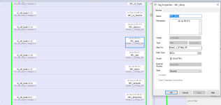
Screenshot 2021-08-04 113811.png
 
It looks ok to me, I don't understand the issue. From a glance, it looks like the XIC on the right is a physical digital input and the output on the right is just an Alias to a UDT used for mapping the physical input to an internal bit. The use of aliases here is a non issue unless you're using IO_AB_Node1:1:I.6 elsewhere in the logic. Then it could be an issue with async, but so long as the code in the machine is only referencing PB1_JibUp, you're fine. It seems like they made alias tags to give meaning to a standard template they use for all of their machines.
 
I agree with David Owen -- this looks OK.

If you go with your first idea, of changing the alias (PB1_JbUp) to reference the I/O point (IO_AB_Node1:I.Data[1].5) or its alias, then two potentially bad things happen:
  1. If the input point burns out and you need to move the wire to a new point, you can't make the PLC code right without a download, which could cost production time.
  2. If PB1_JbUp is used in more than one place in the code, you run into a the chance that it will change state mid-scan, and competing actions will be taken. (this is an overblown concern, IMO, but it IS possible, especially if the programming is done by "non-specialist".)
OTOH, if you go with your other idea, using Parameter functionality, you are merely making Program-scoped instead of Controller-scoped tags for inputs. And these are essentially aliases as well, which suffer from the above issues, as well as making the tags unavailable to other programs (unless you set the tag to Public (assuming v28+))

You may be under a misapprehension that aliasing causing the asynchronous-to-scan issue. It's I/O itself that is asynchronous, regardless of how it's referenced (base tag or alias).
 
However, I am confused as to why a project would have input map routines that map the inputs to the tags that are already aliasing the same input. The screenshot shows this clearly.

What leads you to believe that the tags being mapped to are aliased to the input? I see nothing here to support that conclusion.

The screenshot shows that the OTE tags are aliased to UDTs called Node1_X_IP

The inputs, on the other hand, are (presumably SINT) called IO_AB_Node1:X:I and are aliased to the actual input tag.


I agree with travispedley that the likely reason for this setup is using a template input mapping routine followed by adding aliases with machine-specific names.
 
Last edited:
My understanding of this logic is that we are updating the tag value once in the input map and then again (possibly more than once) when the inputs update asynchronously at some point during the [same*] scan.

I am pretty sure this is where OP's problem is: their understanding of how that logic works in digital PLCs is not correct: the value of that element of the UDT**, and that of the Tag/Alias pointing to it**, will not change during any single program scan except when this input map is executed; so if this input map is called but once at the beginning of a program scan, then the UDT/Tag/Alias will retain the then-current value of the input throughout the rest of that program scan, even if an I/O scan occurs and the value of bit IO_AB_Node:1:1:I:5 changes.

The rungs shown use what is conventionally called the Input Map Pattern***, but perhaps it would better called an Input Buffer, because "buffer" has a more definite connotation of a local snapshot of data, which are copied once, from somewhere else. The word "map" is more ambiguous, and can imply either buffering or an actual connection of another symbol to the same physical bit(s).

This is why something like @Ron Beaufort's beginner's series of YouTube videos is so useful: it encourages us to build accurate mental models about the who, what, where, how, and why of the bits in a PLC. In this case, OP needs to understand there are hard distinctions between

  • physical external inputs,
  • the internal bits written per the then-current state of the input when an I/O scan occurs (whether asynchronously or not),
  • and all other bits used by the program.
There is also a thread somewhere on this forum where Ron discusses input and output forces extensively, which thread further reinforces the concept.

This also brings up another point about the mental models we maintain for ladder logic as implemented in digital PLCs: instructions are executed in order, left-to-right and top-to-bottom; while this will usually be indistinguishable from physically wired ladder (i.e. analog, if you will) logic, to the point that it is often convenient to read it as if they behave essentially the same, it is not the same.

* Implied; added by me
** Node_1_1_IP seems to be a UDT; and tag P1_JibUp seems to be an alias for Node_1_1_IP.Map_05 i.e. for the Map_05 member of UDT Node_1_1_IP.
*** E.g. see this link.
 

Similar Topics

the following popup shows when i tried to open this project: Failed to open File "c:\users\.........\Bulk_Software.ACD The FactoryTalk Directory...
Replies
3
Views
816
Hello Dear Plc expert I can not create the project on studio 5000 or Rslogix 5000, If I chose compact logix CPU (1769 L18ERM BB1B) but If chose...
Replies
1
Views
985
Studio 5000 - strange error , "conflict exists in project verification state" I am trying to upload a test project to our 5069 controller we use...
Replies
7
Views
4,662
I have installed Studio 5000 version 32.00 in Windows 10. It showing error while i create a new project. when i try to finish its gives error as...
Replies
4
Views
2,809
Hello everybody! I have a Studio 5000 project which uses a ControlLogix 5580 (1756-L82e), but do not have that exact PLC model available to test...
Replies
3
Views
1,905
Back
Top Bottom