Unable to read Digital output (DO) from a robot Controller with a PLC (DL205)

latendal

Member
Join Date
Mar 2014
Location
Surrey
Posts
14
Hi guys,

I've hit a major road block developing a machine. I can't seem to read Digital output signals from a robot controller (Fanuc RJ2 controller, pheripheral interface CRM2A) at my PLC (DL205) even though when i monitor Digital outputs at the robot controller it indicates they are being sent out. I've triple checked my wiring and it looks fine (see attachment for wiring details). The funny thing is that i can send DI (Digital Input) signals to the robot successfully. I've tried everything i can possibly think of with no success and any help will be greatly appreciated!! o_O

Noteworthy: I am using the sourcing config for wiring and here is a link for my PLC input http://www.automationdirect.com/static/manuals/d2user/ch2.pdf - page 31
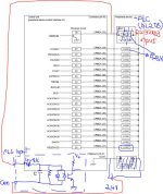
Wiring.jpg
 
Please state which input module you are using in the DL205 rack.

What do you measure using a voltmeter (ON and OFF) between COMMON and the PLC input onthe DL205 system?

Edit - I now see the "D2-32ND3". Sorry.
 
Last edited:
I am using the D2-32ND3 input module and i read 0V between the plc comm and plc input. I read 24.4V between either plc input and voltage source -ve terminal or plc comm and voltage source -ve terminal.
 
Looks to me like the PLC inputs are sinking and the Robot outputs are also sinking. Not sure what the 4.8k is unless you're trying to use it as a pull-up resister.
 
I've even considered the possibility the transistor in my robot circuit may be fried but we have four of this robots and as you must've noticed i have quite a few of this output signals from the robot and it seems very odd to me every single one of them is fried! So i've ruled out that option!
I feel there probably is some config i've failed to either enable/disable on the robot side of things but i've gone through the robot manuals like 6 times and nothing jumps at me! It feels pretty sad to be this close and not know how to move forward!
 
@Jerry Thanks!
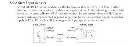
I found this from the PLC manual which give me the notion my connection is okay

 
@bernie i am using more than one of this input modules (PLC). The second is connected to servos and switches and this works fine! So my assumption is my cables should be in order!
 
Also i tried the sinking approach earlier on and got no results as well and it made sense to me because i was at no point supply the 24V DC required by the transistor in the output module of the robot. Here's a pic of that!

Capture2.jpg
 

Similar Topics

Hi All Whenever i try to change the IP address of a compact logix PLC from RSlinx, this message appears to me "unable to read module's port...
Replies
6
Views
4,431
I am able to write on the drive but unable to read actual position. How can I program the messaging to read?? Pls Help!!
Replies
2
Views
3,222
I have been using dotnet and OPC servers (NI and Kepware) to communicate with Allen Bradley Micrologix 1400 PLC on different environmental...
Replies
2
Views
5,805
I am running CCW 13 trying to upload to a micro 820 vers.12 I get an output message OPC server is unable to load project controller. Please help!
Replies
5
Views
266
I've posted this on the ptc forum as well, but no luck with an answer (waiting for my service contract number) I keep getting the following error...
Replies
2
Views
133
Back
Top Bottom