Understanding scan cycle and rung execution order

Works on mine, same logic exactly although a different PLC.
Guess that system is ****.


Thanks, that screenshot gives me another idea. In your editor it looks like they combined the boolean outputs of functions with the ENO variable. That's another workaround for me, if I use an AND function to combine the output with ENO it works fine. No contacts and coils required.


This platform makes more sense when you're used to it. o_O


I went ahead and tried making the same diagram in a generic CODESYS 3.5 install, and it wouldn't allow me to connect the jump to boolean output. It explicitly had to be connected to an ENO or a contact in order to build the project. Anybody with CODESYS want to give this a try?

Screenshot 2022-08-23 163654.png
 
I have read all the posts & still not sure what you are trying to achieve, the coil "NON_ZERO" iseems wrong in it's symbol i.e. are you trying to make that coil if it detects a non zero in the array, or what.
The code you have will energise that coil when it detects a non zero, however, if there is a zero then on the next itteration it will turn it back off so all would have to be non zero to energise the coil, If the compare was changed to equals 0 then it would only energise if all were zero.
If you wanted to detect for the first instance of a non zero then change the jump in the 2nd rung to jump out of the loop,put the return jump on a third rung & on the 4th will be the label for the jump on a non zero, this will then work to test for the first instance of a zero by using an equals compare, so in essence these would need two jumps The pointer however, as it stands at the moment has found the first instance of a zero i.e. say in array [13] so this could be used to point to that variable.
Also, using a coil in a loop without understanding the way it works means that on each itteration it could be in any one of the two states, as on say first itteration it could be on, however, on the next it could be off, so using this in code before or after the loop will depend on the last itteration without a jump out of the loop on the condition required.
Also, monitoring the coil may not give you it's true state as the communications could be only every 5 or 6 scans or by some interrupt by the communications uses, so for example if you set a coil at the start of the program & reset it at the end, if the communication to your IDE was after or before the scan cycle (often is) it would always display as off, however, if the communications for monitoring happens on some sort of random interrupt or during the program scan cycle then the state would change probably randomly.
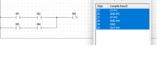
Another thing to think about is how logical operations are scanned, this is usually depicted as left to right top to bottom, this is not strictly true for example
If you have two contacts in series & then another two contacts in series but ored onto an output coil it works in the following manor
Left to right for the first leg
Then left to right sendond ored leg (effectively top to bottom)
Then from that OR left to right for the coil.
As you can see from the attached, the order of operation as just that look at the step numbers on the statement code for that ladder.
 
Last edited:
The code you have will energise that coil when it detects a non zero, however, if there is a zero then on the next itteration it will turn it back off so all would have to be non zero to energise the coil,

Not quite, although perhaps I am misunderstanding @parky's query here.

The output coil is executed exactly once for every scan, and that coil is executed at the end of the loop I.e. After the loop terminates.

The key thing to understand is that the value assigned via the coil is dependent on how the loop terminates, and by terminate I mean the jump backwards to Q2 does not occur. There are two possible causes of such a termination (funky behavior of @modiconguy's system notwithstanding):

1) the loop terminates because the loop found a zero value at some index, 0 to 18, in the array. This occurs when the NEQ evaluates to FALSE, and when that occurs, the loop index is in the range [0:18] inclusive, i .e. a valid index into the array. Note that even though that FALSE result terminates the loop, all of the instructions in the loop execute one last time, albeit with their input rugs having a value of FALSE. So the coil instruction writes a zero to its boolean operand NO_ZEROS_IN_N26.

2) The loop terminates because the loop index exceeds the final array element index of 18, because none of the array valles were zero. In this case, the NEQ evaluates to TRUE, and it is the LT instruction that evaluates to FALSE, preventing the jump backwards to Q2. The execution flow drops through to the coil, for the first time during the current scan, and assigns a 1 to NO_ZEROS_IN_N26, because the input rung to that coil has the TRUE value from the NEQ
instruction's last (19th) execution with an index of 18.

So as noted above, that coil executes exactly once per scan i.e. once per loop, no matter how many iterations the loop executes.
 
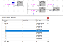
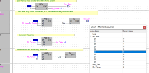
I beg to differ, I have run it, the compare for non zero gives no output i.e. not true, this is because the coil is actually before the loop check and the add, this is how it is supposed to work, normally this type of logic (in older PLC's would not be allowed) i.e. a coil before another logical operation, as I said previously, the left to right rule is not strictly true, so for example assume first pass array[0] is a 1, it will set the coil before it increments the pointer & tests for end of the loop, on the next itteration i.e. array[1], if this is 0 then because the logical output (which is evaluated before the add & jump) it will turn off the coil, then when the evaluation is done because this is not true it does not increment the pointer nor do the jump so carries on with the scan see pics

All non zeropng.png One zero.png
 
I beg to differ, I have run it, the compare for non zero gives no output i.e. not true, this is because the coil is actually before the loop check and the add, this is how it is supposed to work, normally this type of logic (in older PLC's would not be allowed) i.e. a coil before another logical operation, as I said previously, the left to right rule is not strictly true, so for example assume first pass array[0] is a 1, it will set the coil before it increments the pointer & tests for end of the loop, on the next itteration i.e. array[1], if this is 0 then because the logical output (which is evaluated before the add & jump) it will turn off the coil, then when the evaluation is done because this is not true it does not increment the pointer nor do the jump so carries on with the scan see pics

If your PLC does not follow the same order of operation then your logic is not actually equivalent to the original posting, its visual appearance notwithstanding. It should not be surprising that two different sets of logic yield two different results.

To paraphrase drbitboy in post #9, if the model used for how the PLC executes ladder logic instructions in RSLogix 500 is not consistent with the one that is in [insert PLC here] and that PLC's firmware, what appears to be the same logic may not actually be the same.

tl;dr Different PLCs operate differently, while it is very likely that any PLC can construct logic equivalent to this it may be necessary to adjust how it is entered -- for example splitting the OTE off onto a separate rung.
 
That's my point, I would split it & use the jump to jump out of the loop on detection, I have now tried this on a few platforms (well not me but an old colleague of mine has tried it on some) & the result in FBD is the same, the main reason is that many platforms originally (or in older syle ladder) wouldnot allow multiple outs with compares after, many IDE's because they need to keep the code compatible with ladder & compiling to suit the older PLC's use temporary variables to store the RLO, this is normal as the expected RLO driving that coil should do it's job as it is effectively before the compares.
Again I maintain that if (and I say if) the OP wanted to check for an instance of a none zero in a loop then to find at least one instance the loop counter should be after a jump out of the code, like this, so if any one of the array is none zero then it sets the bit as the bit is reset before the begining of the loop so if that none zero changes to a zero it loops to check if there are any more, if not the bit is false, if bit is true i.e. a none zero detected, then anywhere before this code or after it the bit will be true.

None_Zero.png
 
Just to prove my point that the RLO needs to process an instruction as per the way i.e. if parralel or series I put the jump before the coil, because it causes a jump before setting the coil and even though the ENO is true from the jump the coil is not set, parallel branches like the original need to be processed in FBD due to the nature of multiple parallel possibilities.
In the 80's I contracted for a company that were putting in a large steel processing plant, my job was the AFE graphics system, they had developed their own PLC, it was specific to their applications as they developed many of the processes & drives they made, their PLC was programmed in what we now call FBD, to be honest it was a cross between that & the way you program a logo but very powerful, I worked closely with the engineer who designed it, we were working on a protocol which happen to be modbus as this was one of the protocols used by AFE as standard, there was a problem, the engineer from the company I was working for said to their development that their implementation of the protocol was wrong, it worked but it was something to do with not compiling the packets in the chunks expected which caused more transactions, AFE admitted that they knew about the bug but nobody had ever complained, The guy who designed the PLC system vas an extremely clever chap, juring some of the waiting times he demonstrated the PLC code to me, this was far in advanced of any PLC I had come across, I often wondered if he had some input to the advance from ladder to FBD etc.
I do remember querying him on the order of operation on so many branches & effective RLO's feeding back to the left of the code & he said it was a bit of a head scratcher, but when explained it made sense as does the original logic I posted.

None Zero 2.png
 

Similar Topics

I'm trying to understand how the PLC will scan this "For" loop. will the "PhoneNb" variable not increment until all instructions within the "For"...
Replies
0
Views
1,663
I am using Allen Bradley PLC for Ethernet/IP communication. I send any explicit msg request (Get attribute or Set attribute), I observed packet...
Replies
0
Views
75
Took a new job and the controls schemes are fairly old and I'm used to Allen Bradley and Siemens. I'm looking to replace a pair of Superior...
Replies
1
Views
110
Hello Team, I am desperate for some help with an assessment I have as part of a Level 3 general engineering course. I am in a role that is much...
Replies
9
Views
349
Good day is there somewhere i can see the situation and compatibility regarding different firmware revisions. I have a 2711-K5A5, series H and...
Replies
4
Views
215
Back
Top Bottom