Unidrive to PF70 replacement/braking resistor

MJC

Member
Join Date
Mar 2011
Location
ILL
Posts
125
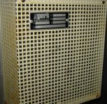
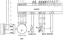
Hello I’m faced with an task of replacing a VFD with external brake resistor, the original drive is a UNIDRIVE 1405 and it’s obsolete. The VFD drives a 4KW motor that is used for lifting a injection head up and down at a continuous motion and speed. Motor is connected to gear box that follows a crank arm. The replacement VFD is a PF 70 CAT#(). The issue that has me scratching my head is size of the brake resistor that is at the below attached picture, why would the brake resistor be such a big size? I always thought that the resistor should be sized to the VFD. All the braking resistors from AB sized for the PF70 are nowhere close to the wattage of the original resistor. Please can anyone help. I’m afraid that is I use the recommended external resistor from AB it might overheat. I’m thinking to just leave the old braking resistor in place and connect it to the new PF 70 but I’m not sure of any limitations.
MTR.JPG
 
Last edited:
As long it's the same resistance as the AB recommended resistor or close to the extra power handling capability shouldn't matter. Just make sure the temperature sensing protection is still ok (properly wired in to stop the drive if there is a problem) and there should be no concern.
 
As long it's the same resistance as the AB recommended resistor or close to the extra power handling capability shouldn't matter.
Thanks Bernie that's the issue I'm faced with the largest braking resistor from AB is not nearly close to the KW of what the original is, I attached the selection guide for DB resistors from AB. The PF 70 CAT Number
20AD011F0AYNANC0 480 volts 7.5 hp
I assume my only option is to leave the existing braking resistor in place and connect it to PF 70, my question is can the PF 70 be connected to this large resistor or am I restricted to limitations.
 
Last edited:
It seems to me that the A-B sizing guide is based on common duty cycles for a given size of drive. You posted the "medium duty" sizing page.

If your application has much higher duty cycles (you called it "continuous motion") then the braking resistor is probably sized correctly (or better) for your actual application.

You've referred to the existing braking resistor as a "big size" and "nowhere near" the wattage of the resistors in the A-B selection guide.

Put some ohm and watt numbers to it and I'm sure that some experienced application guys will be able to step in.
 
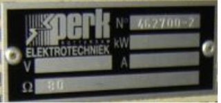
Ken Thank You for your response, the existing braking resistor is a 4kw 80 ohm as pictured in the schematic post #1. The largest selection that I can make from the medium duty dynamic braking resistors is the (AK-R2-120P1K2) which is a 260 watt 120 Ohm,
You posted the "medium duty" sizing page

Are there any heavier duty DB resistors that you can recommend.
 
Last edited:
The braking resistors I have come across have two ratings, the peak power rating and the continuous power rating. e.g.
Can you post a picture of the existing brake resistor?

res.JPG
 
Keep in mind that the drive doesn't really know or care what size the resistor is. More important is the resistance matches what the braking IGBT can handle. As long as the drive can handle a resistance as low as 80 ohm there is no reason not to leave the original in. The higher the wattage value the more energy it can dump over a certain period of time.

There are of course parameters in the drive to allow it to protect the regen resistor (internal mathmatical model to keep track of output power and time) and these should be adjusted as well.
 
It appears from the braking resistor chart that you posted that the 7.5hp 480V drive is capable of handling a resistor down to 73 ohms. That would say that the 80 ohm resistor is ok. That the existing resistor is a little higher in ohms simply means that the absolute maximum braking power in the system would be a little less at 80 ohms than it would be at 73 ohms. As long as you don't expect to need all 4kw from the motor in braking, you will be ok.

As to the wattage, someone seems to have erred on the safe side when sizing the original system and installed a brake resistor with wattage that matches the motor kw. This provides a braking resistor with enough heat dissipation for continuous full kw braking. Other than unwind tensioning drives, this continuous braking is very rare. At any rate, the higher wattage resistor doesn't hurt anything and will just run nice and cool.

I'd say you are good to go using the existing resistor.
 
The V, A and kW ratings are blank - how do you know the rating of this resistor is 4kW (apart from the schematic)?

res.jpg
 

Similar Topics

hello everyone, trying to find a way to read/write memory of the PLC that is inside Unidrive M700 over Ethernet (modbus TCP) using device/server...
Replies
0
Views
561
Greetings experts, We have a 'Control Techniques' Unidrive 3405 in an older machine. It appears that the drive parameters are recorded in a .CTD...
Replies
0
Views
726
Hi We intend to replace our LENZE EVS9326 EP with a Control Technique Unidrive SP. The machine is a simple one; PLC send ABZ pulses to the drive...
Replies
3
Views
2,042
Looking for a Modbus address manual for M700. Modbus address is same as the Parameter number for 16Int parameters. But it is different for 32Int...
Replies
2
Views
1,994
Hello, new here, so let's start :) I am having some issues with kinco mt series hmi, mt4414te. Kinco and unidrive sp are connected via modbus...
Replies
14
Views
3,950
Back
Top Bottom