Unwind/Rewind Math Questions

Blue92

Member
Join Date
Sep 2019
Location
N/A
Posts
27
Hi all. First time programming a machine of this type. A center driven unwind feeding to a center driven rewind. No dancers or load cells, just used to pull coiled metal off of a core. I have laser diameter sensors on each roll, so calculating speed based on circumference is easy enough. Where Im getting hung up is the math behind getting the machine to decelerate so that we end up with the same diameter roll on the rewind as we started with on the unwind, minus the core thickness. I would like for the machine to reach a certain point then start to decelerate until it reaches the finished roll size. Any suggestions?

I read up on distance to stop formulas and jerk rates and what not but got lost quickly. Linear distance of material doesn't really matter here, since Im just pulling material off of a core and winding it back up sans core. I think we can do it based on roll diameter minus core thickness just unsure how.

The unwind/rewind shafts only spin at a maximum 400 rpm, accel/decel rates will be operator inputs, but assume pretty slow.
 
getting the machine to decelerate so that we end up with the same diameter roll on the rewind as we started with on the unwind, minus the core thickness.


Do the two cores, unwind and rewind, have the same diameter?
 
Last edited:
Part I

A model for the cross-sectional area of a roll:
A = π × d2 ÷ 4

A = (L + Lp) × t​
Where
π = PI
A = cross-sectional area
L = Length of material around the shaft or [shaft + core]; L is also equivalent to circumference
Lp = Phantom length, constant, representing equivalent length of material theoretical wound about nobbut itself (no core or shaft) that would make a roll of the same diameter as the shaft (+ core).
t = average thickness of a layer on the roll, including any space between layers, a measured constant, which is an implementation detail.
d = diameter of the roll, measured
Differentiating:
dA = (π × d ÷ 2) × dd

dA = t × dL​
so
(π × d ÷ 2) × dd = t × dL
rearranging
(π ÷ (2 × t)) × dd = dL ÷ d
(L ÷ d) is the the ratio of circumference to diameter, which is angle, θ, so (dL ÷ d) = dθ,
(π ÷ (2 × t)) × dd = dθ

k × dd = dθ, where k = π ÷ (2 × t), a constant
Converting to time derivatives
k × dd/dt = dθ/dt

k' × dd/dt = RPM
because dθ/dt is rotation rate, which scales to RPM; k' is k with the scaling factor from (radian/[time unit]) to RPM included.

N.B. k and k' are negative, assuming dθ/dt and RPM are positive.

End of Part I
 
Part I (updated)

Updated a few things, also disambiguated thickness and time variables, and used a better font:

An ideal model for the cross-sectional area of a roll:
A = π × d2 ÷ 4

A = (L + Lp) × h
Where
π = PI i.e. ratio of a circle's circumference to its diameter
d = diameter of the roll, measured in real-time
A = cross-sectional area
L = Length of material around the shaft or [shaft + core]; L is also equivalent to circumference
Lp = Phantom length, constant, representing equivalent length of material theoretical wound about nobbut itself (no core or shaft) that would make a roll of the same diameter as the shaft (+ core).
h = average thickness (height) of a layer on the roll, including any space between layers; this is a measured and/or empirical constant; determining its value is an implementation detail.
Differentiating:
dA = (π × d ÷ 2) × dd

dA = h × dL
so
(π × d ÷ 2) × dd = h × dL
rearranging
(π ÷ (2 × h)) × dd = dL ÷ d
(L ÷ d) is the the ratio of circumference to diameter, which is angle, θ, so (dL ÷ d) = dθ,
(π ÷ (2 × h)) × dd = dθ

k × dd = dθ, where k = π ÷ (2 × h), a constant, probably determined empirically
Converting to time (τ) derivatives:
k × dd/dτ = dθ/dτ

k' × dd/dτ = RPM
because dθ/dτ is rotation rate, which scales to RPM; k' is k with the scaling factor from (radian/[time unit]) to RPM included.

N.B. k and k' are negative, assuming dθ/dτ and RPM are positive.

End of Part I
 
Part II, deceleration model

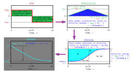
Using that ideal model, here is a jerk-limited profile to bring the rate of change of diameter (d); starting at diameter D0 and time τ = 0; ending at diameter Dcore and τ = Δτ. This is taken from this wikipedia link.
image.png
Jerk, d3d/dτ3
Jerk is positive JMAX for the first half of the period Δτ, and negative JMAX for the second half:

τ < Δτ / 2:
= +JMAX
τ ≥ Δτ / 2: = -JMAX
Acceleration, d2d/dτ2
Acceleration is 0 at the start and end of the period Δτ, and driven by Jerk above.

τ < Δτ / 2:
= JMAX × τ
τ ≥ Δτ / 2: = JMAX × (Δτ - τ)
Velocity, dd/dτ
Velocity starts at (400RPM ÷ k')* at the beginning of the period Δτ, and is zero at the end, and is driven by Acceleration above.

τ < Δτ / 2: = (400RPM
÷ k') + JMAX × τ2 ÷ 2
τ ≥ Δτ / 2: = -JMAX × (Δτ - τ)2 ÷ 2

* N.B. assumes the process, which is near the end of a rewind, is limited by the smaller diameter of the unwind roll running at maximum speed i.e. 400RPM

N.B . the rate of change of the diameter is negative, as is the constant k'
Diameter, d
Diameter is D0* at the start of the period Δτ, and Dcore at the end.

τ < Δτ / 2: = D0 + (400RPM
÷ k') × τ + JMAX × τ3 ÷ 6
τ ≥ Δτ / 2: = Dcore + JMAX × (Δτ - τ)3 ÷ 6
N.B. as request by OP, this is a model based on the deceleration of the measured diameter, not the length of material remaining on the unwind shaft + core. The diameter and length are related (by square root and the phantom length), so the characteristic will be different using diameter instead of length, but the end point will be the same, because remaining length will be zero when the measured diameter is equal to Dcore.
 
Part III

Here is a graphical version of the jerk-limited acceleration model. Because both Jerk and Acceleration (of diameter) start and end at zero, and the Velocity (rate of change of diameter) starts at a known value (400RPM÷ k') and ends at 0, the math is fairly straightforward, with the area of each curve over the [0:Δτ] deceleration period being (i) trivially derived graphically from symmetry, and (ii) equal to the change in the quantity of the next curve.
image.png
 
Last edited:
@drbitboy, what happens if the acceleration/deceleration limit is reached? Then there is an intermediate constant acceleration or deceleration phase/state.


Patience, Peter, patience: I only made it to Part III so far.

We still have to set the parameters, which is where we deal with that problem. Then there is coding the algorithm, which involves solving d =
D0 + (400RPM ÷ k') × τ + JMAX × τ3 ÷ 6 for τ with a known (measured) value for d.

There is also a torque limit
, which will involve estimation of inertia, but that should overlap with any acceleration/deceleration limits.

Bottom line answers to your queries: (i) the answer to "what happens if the accel/decel limit is reached" is that we use that constraint when setting the Δτ over which the decel happens
and the JMAX value; (ii) I chose to do this without a "step 6" (cf. the wiki) intermediate constant acceleration phase/state, or stated another way its duration is zero. Obviously, if we increase JMAX (jerk a.k.a. jolt) so there is a constant acceleration phase of non-zero duration, then that changes the details, but not the basic approach, and the graphically-derived integration is still trivial because the velocity would have a linear characteristic during the constant acceleration phase, which would maintain the symmetry.
 
Last edited:
Actually, what if we don't care about jerk/jolt and constant acceleration (infinite jerk) is good enough? That solution is simpler.
 
Last edited:
Actually, what if we don't care about jerk/jolt and constant acceleration (infinite jerk) is good enough? That solution is simpler.

Yes, lets do that. Chances are the customer may want to stop before the roll runs out and jog it in the rest of the way anyways.

Also, Im way lost in all of that differential math haha.
 
Since you are only winding metal you probably will get by with that. I wonder if it will make much difference is some layers are wound a little tighter than others. I wouldn't do that if winding something that stretches. Keith might have something to say about this.

@debitboy, you dodge a bullet. It is amazing how much effort you have put into so far. Taking into account all the different cases for 3rd order ramps gets messy. I wouldn't want to write that code in a PLC.

Anyway, I was preparing to pop a whole lot of popcorn but not now.

If the linear ramps don't work, then it is time to get a real motion controller. Trying to do 3rd order ramps in a PLCs is asking for abuse.

https://deltamotion.com/peter/wxMaxima/Seg1234567.html
And that is only ONE case.
 

Similar Topics

I have R&D project that I am working on. It consist of an unwinder and a rewinder. The goal is to unwind the material from the unwinder and rewind...
Replies
27
Views
15,464
Hi all... I have a machine that processes rolls of rubber coated fabric product through a slitter and rewinds the slit stock. The current PLC...
Replies
11
Views
8,954
Typically what sort of DC motor is normally used for this application. I ahve a customer that wants to upgrade his existing SCR controller with a...
Replies
1
Views
3,292
I'm doing my first wind/unwind project, and I need some input from someone with more experience. ...I'm getting my butt kicked trying to control...
Replies
38
Views
11,299
I was working at a customer's location yesterday and I came across an intermittent issue on their wind/unwind machine. I'm still trying to figure...
Replies
1
Views
1,649
Back
Top Bottom