Using Wonderware to access MicroLogix 1100's via Radio?

Well, this modbus stuff seems to be pretty strange from what I'm used to. Maybe you can help me out here.

Let say, for example, that in my remote MicroLogix 1100 plc, I have a tower level set to be N7:10. In the PLC's Channel Config, I have it setup as a Modbus RTU Slave, with a 7 in the Holding Registers (4xxxx) field.

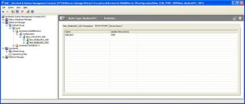
I have the COM_PORT->New_ModbusPLC_000 driver set up.. Not sure if anything needs to be set specifically there, but it all looks okay.

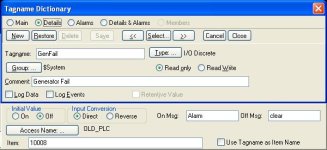
Alright, so in Wonderware, how do I setup my tower level tag? I originally went through and used all of the PLC addresses for my tag Item Name, so TowerLevel is set to N7:10 in Wonderware. Do I need to make the Item Name some funky modbus address instead for all my tags?

Thanks!
 
alright, from the top, do you have the rtu address set to the same thing in both plc and the dasmbserial driver?

next, you should use the modbus address in wonderware. I dont have a logic file in front of me but if you have n7 set as the holding register data then n7:10 should be 40010, I think. I dont remember if the modbusaddresses start out as 0 or 1 based. so it may be 40010 or 40011. thats where using the modbus poll program that I linked earlier comes in very handy, you can poll multiple addresses which helps you determine whats what. why dont you post a copy of the program and I can help you a little better?
 
Thanks for the replies.

Yep, since I have two radio stations, I have two ModbusPLC objects installed under the COM_PORT object in the System Management Console. The first one has a node address of 1, and the second has a node of 2. This matches the node addresses set in the RTU Slave configurations of the Micrologix 1100's.

(I assume that I need to set a different topic name in each of these objects so that Wonderware knows which radio to poll for which data.)

I will try and upload the program in a bit though. Still rearranging the addresses so they can be accessed by the modbus files.
 
its best to add a new data file, lets say n50 and b20 and then just map the data into the new files so that everything will be in order and you dont have the driver jumping all over for different modbus addresses.

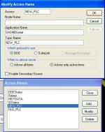
the topic name needs to be the same as the access name in wonderware. you dont have to key in any individual item names either. take some screenshots of your driver setup while you are at it.
 
Ah very helpful info so far. Yeah, I have created new data files for my modbus comms (b11 - coil, N12 - holding, N13 - input).

It's a little confusing as to what the difference is between input register and holding register. So let's say i have some integer setpoints on wonderware that I want to write to one of the MicroLogix 1100's. How would I go about that. Do I set those setpoints as 3XXXX values in wonderware and then have a copy instruction that copies N13 to my actual setpoints in the PLC?
 
Last edited:
setpoints or anything that can be written to should be setup as holding registers, 4x. holding registers can be read and written to. input registers 3x can only be read. we usually just set everything up as holding registers, but either way is fine.

same thing with coils and inputs. coils, 0x can be read or written, and inputs, 1x can only be read. alarm status bits should be setup as inputs, and bits used for control should be coils. unless you are using some sort of bit packing in holding registers.
 
Update: Alright, Ive got the PLC's in the mail today, and finally got them all setup and configured. I used the Modbus Poll program that you linked me, and it seems to be working well. I'm able to read and write to the PLC over a serial cable connected to the computer directly (I figure I'd get everything working with a normal serial cable first before adding in another variable like a Radio Modem).

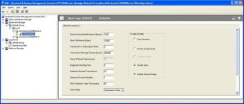
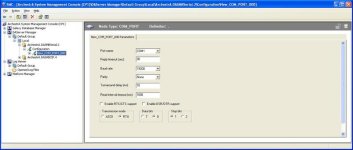
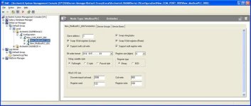
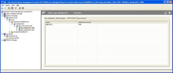
Unfortunately, when I switch over to wonderware using the serial driver, I do not get any values in my tags, so there must be some error in how I've setup the driver or the tags. I'm attaching screens of how I've setup everything so far. I'll attach the rest of the screens and a zip file of the PLC program in the next post.

Thanks!!

1.jpg 2.jpg 3.jpg 4.jpg 5.jpg
 
Here's the rest of the screens and the plc program for one of the stations.
(Ignore the comm failure code in LAD 2. I haven't worked on that section yet heh...)


Also, looking in the log file for the archestra system management console, I see the following message: "PLC poll message timed out on port COM1, revoking message"
"COM1 Slave 1 encountered exception error 03: ILLEGAL DATA VALUE"

I noticed that the Modbus Poll program would say Illegal data also if I expanded the quantity out too far. Maybe I need to limit the Block I/O size numbers in the modbus driver?

NEW UPDATE: Well...it appears to be working! I changed the "Register size (digits):" from 6 to 5 in the modbusPLC object driver, and it worked. /shrug.

Next step: add the radios...

6.jpg accessname.JPG tag1.JPG
 

Attachments

  • New_RTU.zip
    25.8 KB · Views: 2
Last edited:
Hmm, still getting a lot of these: "PLC poll message timed out on port COM1, revoking message" Seems to be about every 30 seconds exactly (thats the driver's Reply timeout (sec)). And that's with a straight serial cable connected...
 
Last edited:
I would try and back off of the 1 second poll rate. go up to 5 seconds, set your timeout to 5 seconds, 30 is too long.

did you get any failed polls while using the modbus poll program?
 
I would try and back off of the 1 second poll rate. go up to 5 seconds, set your timeout to 5 seconds, 30 is too long.

did you get any failed polls while using the modbus poll program?


I'll try that. I didnt get any failed polls with the modbus program. I think it was set to communicate every second. 0 errors.

Edit: I'm confusing myself here. Alright, so which value should I back off? the Device Group Update Interval in the Global Parameters?

I have a continuously running comm timer in Wonderware that gets reset every time it reads from the PLC. It gets reset every 20 seconds...every time. So it's like its only polling the PLC every 20 seconds. :\
 
Last edited:
try and maybe move the turnaround delay up, try 500ms. thats the same thing as delay between polls on the modbus poll driver, I think 500 ms is the default for that on modbus poll. also, what type of device type did you choose? maybe try quantum plc if thats not what you chose.
 
Im using the MODBUSPLC device type. I figured that'd be a generic modbus plc instead of a specific modicon plc type.

Well, I figured out what the poll timeouts were. It was the modbus driver trying to find slave #2...duh. I had a straight serial connection between the computer and PLC #1. No way to hook up plc #2 as well. I disabled the second driver, and all error messages went away.

Something that is really bugging me out is that my comm timer doesnt seem to be working. I have a simple "While Running" application script that updates every 1000ms.

Timer = Timer + 1;

IF (CommReceived) == 1
THEN Timer = 0;
CommReceived = 0;
ENDIF;

IF (Timer) >= 300
THEN CommAlarm = 1;
ELSE CommAlarm = 0;
ENDIF;

Pretty simple... The "CommReceived" integer is always set to a 1 in the PLC, so whenever the modbus driver reads from the PLC, it should see that it's a 1, and reset the timer as well as the CommReceived value to zero. If it doesnt see a 1 for 300 seconds, then there is a comm alarm.

So here's where it gets weird. It seems to work just fine while the serial cable is plugged in. Resets the timer every 5 seconds or so. But, if I unplug the cable, the log file reports that it is going to Slow Poll mode and there are timeouts every 10 seconds as expected. BUT...the freakin comm timer is reset every 10 seconds as well. I added a numerical display on the screen to watch "CommReceived" and its turning to a 1 every 10 seconds! How is that possible? Is there a modbus buffer or something that it could be reading the value from? Ahhhh!
 
Last edited:
Im using the MODBUSPLC device type. I figured that'd be a generic modbus plc instead of a specific modicon plc type.

Well, I figured out what the poll timeouts were. It was the modbus driver trying to find slave #2...duh. I had a straight serial connection between the computer and PLC #1. No way to hook up plc #2 as well. I disabled the second driver, and all error messages went away.

Something that is really bugging me out is that my comm timer doesnt seem to be working. I have a simple "While Running" application script that updates every 1000ms.

Timer = Timer + 1;

IF (CommReceived) == 1
THEN Timer = 0;
CommReceived = 0;
ENDIF;

IF (Timer) >= 300
THEN CommAlarm = 1;
ELSE CommAlarm = 0;
ENDIF;

Pretty simple... The "CommReceived" integer is always set to a 1 in the PLC, so whenever the modbus driver reads from the PLC, it should see that it's a 1, and reset the timer as well as the CommReceived value to zero. If it doesnt see a 1 for 300 seconds, then there is a comm alarm.

So here's where it gets weird. It seems to work just fine while the serial cable is plugged in. Resets the timer every 5 seconds or so. But, if I unplug the cable, the log file reports that it is going to Slow Poll mode and there are timeouts every 10 seconds as expected. BUT...the freakin comm timer is reset every 10 seconds as well. I added a numerical display on the screen to watch "CommReceived" and its turning to a 1 every 10 seconds! How is that possible? Is there a modbus buffer or something that it could be reading the value from? Ahhhh!

if the integer in the plc is always 1 then wonderware reads the 1 and holds that value. wonderware isnt going to change it to zero unless it sees zero in the plc.

why dont you use the comm status functions that are built int the driver. update interval and comm status should be useful. you can also look at error counts if you want.
 

Similar Topics

Hi; In my O/G facility we are using Wonderware Intouch ver 9.5 for SCADA. We need to automate the process of exporting realtime process values for...
Replies
2
Views
2,531
Hey guys, I'm working on an existing system where the old programmer (from like 25 years ago) used a bunch of conditional scripts in Wonderware...
Replies
2
Views
1,779
https://www.theregister.co.uk/2018/01/15/meltdown_ics/ Here's another thread with an RSWho issue...
Replies
1
Views
2,071
I am building a new galaxy for a customer and I am trying to test things as I go. All my Ethernet PLCs are OK, but I have a test PLC5 in my...
Replies
1
Views
2,158
I operate a distillation column for Argon gas. It has a pressure controlling valve that cools a condenser at the top of the column with nitrogen...
Replies
4
Views
2,272
Back
Top Bottom