VFD Amp value filter

trueninjalo

Lifetime Supporting Member
Join Date
Oct 2015
Location
Ohio
Posts
40
I am trying to find the operating limit range of a few conveyors. In the event one of them breaks I want to see the abnormal value and use this for an alarm trigger. For example, conveyor SB19 is running at 1.29-1.3 amp when it is empty, and its peak seems to be 1.4 amps (so far) when loaded. The lowest value so far while running was 1.29.

I have made some what of a band pass filter in the logic and I would like to refine it. When the conveyor stopped I got a low value of 1.28 amps. While this isn't a big difference it still isn't accurately representing the situation. However, the line may actually go this low while running so I don't want to ignore this value.

Please review the photo and let me know if there is a better way to go about this. For the low filter I watched the lowest value for about 30 minutes and subtracted 5 (which gave me 125) and made this my low monitor limit. If the line stops then value drops to 0 in less than a second (no ramps). I did the opposite for the high filter.

Background: A conveyor broke and the start stop sequence didn't stop the line properly. The photo eyes weren't covered properly to trigger the jammed state, and the stop cascade never triggered. My first thought was to create an activity monitor for all conveyors and if downstream conveyors have no activity while upstream do, then trigger a blocked state. This however wont stop the line fast enough so monitoring the VFD current seemed like a better way to catch it.

Thanks for any assistance.
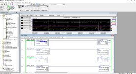
SB19_01.jpg
 
Perhaps a rotation sensor on every conveyor would be a better option.
Drive currents can change over time due to wear, bearings etc, also loading on the conveyor for example an empty conveyor may require less current, however, it is not broke. You also have startup current to consider i.e. mask initial startup current.
 
Thanks for your input. You mentioned the change over time and i thought of that as well. One of the secondary reasons for monitoring current is also for preventive maintenance such as wear. The lines also get sticky and if they aren't cleaned they will break links. so i want to get a normal reading and range so I can identify if the line need maintenance before they break.

You also mentioned the lines being underload. The High and Low tags will hopefully represent when the line is under full product load and empty.

Lastly you mentioned inrush current. I thought that might be an issue. If you look at the trend it does appear to have a small inrush spike. I think i can put a 1500ms TON triggered by the vfd.running tag and use the done bit in series with the running bit to enable the filter. This way I can delay the high/low monitoring 500 ms after the line starts and stop monitoring once the running bit is false. That should remove the transients from the filter.

Thoughts?
 
Yes I agree, a small timer to allow startup, again one thing that would be difficult in using sensors on a star wheel is getting the timing right so if the conveyor was getting sticky it would be a lot of work to get the right mask timing for the pulses, but then again you will have the same problem with current monitoring I think. It will be a trial & error exercise to get either right.
 
What is the final goal of this "performance"?
What are the requirements and restrictions (by level, by time)?
Explanation:
curves #1 What will you do with SB16 at t=1:03:50 and SB17 at t=1:04:00? What will you do with SB16 and SB17 at t=1:07:50?
 
First let me say this if you wait until the conveyor belt breaks you have already lost and nothing you can do after that will be of much value.
I assume that al you conveyors are run from a VFD
The best way to handle it is to monitor all the VFD output amps Most VFD’s allow you to monitor the output amps.
Interlock each conveyor with the to the one that it feeds and the one feeding it
Start them in reverse order discharge end first. Don’t allow the feed conveyor to start until the conveyor downstream is confirmed running at or just above the no load amps before you start the conveyor feeding into it. This should continue until all conveyors are running then you may start feeding them with the load.
Then monitor the amps on each conveyor. Here’s where it get a bit tricky you need to determine the maximum expected load on each conveyor, then before the load get to high start slowing down the feeds until the amps are within the operating range, then when any conveyor amps exceeds the normal max load then do an shutdown on the one feeding it. Preferred method would be a Base Block of a short ramp with a breaking resister to stop the load as quickly as possible. This same stop should be implemented on all conveyors back to the start. Allow the conveyors downstream to continue running empting the line. If you do this right you should be able to shed the load before it becomes a problem.
I normal operation the conveyor could stop and restart automatically before any belt breaks
I would also. I recommend that you use speed switch on the tail stock of the conveyors to detect any slippage due to overloads or belt tension. And here again shut down or sow up the conveyor feeding it.
It takes a little time but is set up correctly the system will self correct for load.
I have done this many times on grain elevators and grain handling systems, when I sense a high load I slow the feed we don’t see belt slippage or broken belts anymore. I also on a stop command I run the conveyor for a time to empty them. That way I don’t restart them under load. I have found that we have far less problems this way.
I hope this helps
 
GaryS thanks for the response, to answer your questions,

First let me say this if you wait until the conveyor belt breaks you have already lost and nothing you can do after that will be of much value.
Obviously

I assume that al you conveyors are run from a VFD
Yes

The best way to handle it is to monitor all the VFD output amps Most VFD’s allow you to monitor the output amps.
Thats what started me down this path

Interlock each conveyor with the to the one that it feeds and the one feeding it. Start them in reverse order discharge end first. Don’t allow the feed conveyor to start until the conveyor downstream is confirmed running at or just above the no load amps before you start the conveyor feeding into it. This should continue until all conveyors are running then you may start feeding them with the load.
This is how it is running but not at amps but by freq

Then monitor the amps on each conveyor.
This is the point we are at.

Here’s where it get a bit tricky you need to determine the maximum expected load on each conveyor,
This is what brought me here

then before the load get to high start slowing down the feeds until the amps are within the operating range, then when any conveyor amps exceeds the normal max load then do an shutdown on the one feeding it.
?

Preferred method would be a Base Block of a short ramp with a breaking resister to stop the load as quickly as possible. This same stop should be implemented on all conveyors back to the start.
All drives are 2 amp PF525. the amplications are too small to warrant a breaking resistor with the exception of sb14 which is a 5 amp PF525 which does have the breaking resistor and work as you described. You can see in the trend how quick the start/stop response time is.

Allow the conveyors downstream to continue running empting the line.
If you do this right you should be able to shed the load before it becomes a problem.
This is the current operation

In normal operation the conveyor could stop and restart automatically before any belt breaks.
They usually do start and stop automatically but amp monitoring is a new method I am introducing. Were currently use photo eyes (PEs). Most conveyors have two PEs at the beginning and ending of the conveyor but some conveyors only have one PE in the middle. The belts are old and consist of hundreds of links each. The break occur due to wear and sourcing enough to replace and entire belt is cost prohibitive at this time. The goal is to detect a break quickly. This cannot be done easily (or maybe obviously) with PEs alone


I would also. I recommend that you use speed switch on the tail stock of the conveyors to detect any slippage due to overloads or belt tension. And here again shut down or sow up the conveyor feeding it. It takes a little time but if set up correctly the system will self correct for load.
Load monitoring is a goal and we aren't quite there yet. I am trying to find the normal load range as you suggested earlier. I recognize my method to find this load range is crude. Before I reinvent the wheel though, I want to see if someone else may have a wheel for me to mimic lol. Sometimes it is best to get a fresh set of eyes. Going forward I will try to explain the situation better.

I have done this many times on grain elevators and grain handling systems, when I sense a high load I slow the feed we don’t see belt slippage or broken belts anymore. I also on a stop command I run the conveyor for a time to empty them. That way I don’t restart them under load. I have found that we have far less problems this way.
I currently have an systems to vary the speeds and durring startup and accumulation. the goal (one of many) is to use amps to detect a break and to detect when the line needs cleaned. if i find my conveyors are pulling higher amps then I can get the lines cleaned of product.

I hope this helps
Thank you for your input.
 
jbrandt, thanks, the first data sheet I found was helpful. I will try to program a rate of change trigger. That should find a broken link when it occurs. I'm sure I will have false positive in the beginning, but this seems like a good path to follow.
 
Would it not be simpler to create a timer that is set on PE1 and reset on PE2 and if the conveyor is running and the timer times out then you know there's a problem?
 
Would it not be simpler to create a timer that is set on PE1 and reset on PE2 and if the conveyor is running and the timer times out then you know there's a problem?
bb76,
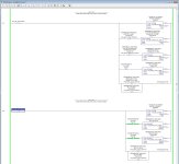
We kind of use that now, but its not a set/reset situation. the timers are set by running and blocked signals from VFD and PEs. This catches jams well enough, the problem, is that it doesn't catch a break fast enough. With a jam, we have accumulation for upstream conveyors. As the timer runs, they continue to fill up with product, that way, the faster the jam is cleared the less conveyors shut down. This reduces delays over time. However, if a break occurs, the line running still pushes the cases along the guide rails to PEs and it takes too long for the timers to realize there is a problem. I think I am headed in the direction of you idea though. Yesterday I started an active state monitor and plan to use it to help by letting me know if downstream conveyors are still moving product while upstream are active. It is similar to your set/reset but not quite. I assume if SB18 is active and SB19 is not active for a set time, then something is wrong. A photo is attached to this reply, let me know your thoughts, Thank you.

active_tmr.jpg
 

Similar Topics

I just finished analyzing some blower test results. This uses a high-speed permanent magnet synchronous motor (25,000 rpm) controlled by a VFD at...
Replies
5
Views
1,803
i have a motor (3.7kw ) which draws current around 5amps when running on DOL, same motor when running with vfd on max speed draws 12.5 amp...
Replies
6
Views
3,416
Hello, first of all let me state for the record that I'm not a tech of any kind, I have limited experience with industrial automation devices, so...
Replies
3
Views
99
Sorry in advance for the long post, but this requires a little back story. I work in a facility with a couple hundred VFDs Most are in a web...
Replies
14
Views
229
Customer want to use contactor for their 5HP motor blower application. im leaning to VFD. anyone use contractor for blower application...
Replies
9
Views
205
Back
Top Bottom