The example shows writing 32 bits to coils, not to Holding Registers.
The table below (poor example, but the only one I have, it is a vendor-specific table with defined analog outputs, which are Holding registers) shows the most commonly used Modbus commands. Function 0F hex (16 decimal) writes to multiple registers, where each registers is 16 coils.
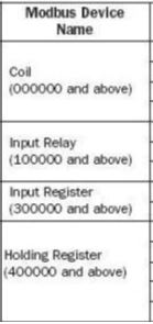
The Coils reside in memory area that starts at 000000. When the Function code is specific to reading/writing coils, then addressing starts at the memory area for coils, not for Holding Registers. The leading numeral 4, as in (4)00001, defines the register as a Holding register, but the leading numeral is not part of the Modbus packet; it is the Function 03 that defines the indexed offset 'address' for Holding Register memory area.
You'll have to interpret the command word bit-by-bit to see what it's doing, and make appropriate changes, but the example clarifies that the command word resides in a Danfoss as a coil register, not as a Holding Register.