Config an analog card

rojay

Member
Join Date
Sep 2011
Location
Cleveland
Posts
11
Why is it that we have to put a line of code in to config an analog input card? How do I do this for an 1762-IF4, and a 1762-IF2OF2? All help is appreciated.
 
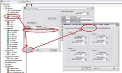
Click on the Advanced Config button in the IO configuration, pick the Analog Configuration tab, and configure the analog IO there.

A09282011-1.jpg
 
Alaric, I appreciate the reply, and I have done that. My question is why there is a rung before my analog inputs that is triggered by a normally open contact S:1/15 that copies the value of 2565 to #O:5.0, which is the location of the input card. The description above this rung is "Initialization for slot 5 1746-NI8 channel input class 1"
 
Hard to tell why they do that without seeing the rest of the program. It is not a necessary step for using analog inputs/outputs in general, but it may be necessary because of something in the program, how it was written or what it is controlling.

It only does it on the first pass (first scan after the processor goes into run mode), so it may be something to initialize what ever it is controlling, or to avoid errors in logic due to the process just starting. Or it could be setting the output state to what it was when it powered down, what ever was loaded into N9:0

Edit:
And it seems that is an analog output, not an input. O:5.0, not I:5.0
 
Last edited:
RSLogix will insert that logic for you on some processors. What processor do you have?

Your first post would indicate a ML1200 but a 1746 card is for SLC500's.

Are you converting from one processor to another?

Post your program if you can.
 
Last edited:
I suspect that it is what Mickey mentioned, the program was converted from a SLC500 to Micrologix. In the SLC500 you had to write a configuration word to the module. You could do that by setting bits in the output image file and hope someone didn't change them or you could program a write to the output image file. That isn't necessary in the MLX. In 1762 modules the configuration of the module is written at the go to run event before the program begins, so any programmatic changes will have no effect.

For third party cards such as those from Spectrum Controls refer to the card manual.
 
Last edited:
I didn't know that. I've only used 5/03 through 5/05 with analog cards though. Never had a configuration in the ladder like the one posted. Maybe it's earlier processors?
 
Some 1746 analog modules do not require software configuraton.

Look at the screen shot rojay attached. The rung comment indicates it is for configuring a 1746-NI8 module, so the original program was definitely a SLC500 program. The rung copies 8 words from N9:0 to O:5.0. Were you to attempt to do that on a Micrologix 1762-IF4 you would get an error because no output word is allocated in the IO image table for that module.

If you used the configuration tool, RSLogix would create a file and insert the rung for you. To see this open a new blank RSLogix500 project, pick a SLC5/03, 04, or 05 processor, insert an NI8 module, click advanced config, and then configure. Configure a few of the channels as desired, then click the OKs. Logix should insert a rung for you and add a configuration file. If you opened the configuration file and changed the radix to binary you can see that the bits are set just like you would set them if you followed the configuration tables from the IO modules manual. Eight input words and eight output words are allocated to the module in the IO image table.

However if you inserted a 1746-NI4 module you wouldn't get a configuration option because that card is set up using dip switches and doesn't support as many options. In the case of the NI4, 4 input words and no output words are allocated for the IO image table.
 
Thanks for all the responses everyone. The complete story here is that I am writing a new program for a ML1400. I am copying some logic from a SLC5/05 program, and yes the old program does send a value of 2565 to "#O:5.0" to initialize input card 5. From what I am reading, in the ML1400 I do not need to do any of that. I appreciate all of your help.
 
Rojay,

Some other things to watch for when converting SLC to ML:


  • ONS vs OSR. The SLC has only the OSR instruction. The ML inline one shot is ONS. OSR and OSF are output instructions in the ML platform.
  • STIs are configured using the funciton files, not S:30-31.
  • Long data type. The ML supports 32 bit integers and math as L files.
  • DDV - because it supports 32 bit math the ML does not have a DDV instruction.
  • The S:13 and S:14 math register work differently because of the 32 bit capability.
  • The ML supports a PD data file type for PIDs similar to the PLC/5
  • The ML supports a MG (Messaging) data file.
  • Don't use S:37 thru 42 for date and time. Use the RTC function file for date and time.
  • Timers add a millisecond time base in the ML platform.
There are probably some others that I'm not remembering.
 
Last edited:

Similar Topics

I might be missing something simple here but we've set some scaling up on our analogue input cards (4-20mA ranged HighEngineering = 100...
Replies
6
Views
2,632
All, I need some assistance ASAP. I am not sure how to configure IV3+ analog input for 0-10 vdc. Is there a jumper or something that I need to...
Replies
2
Views
1,398
Hi, thanks to all those who replied me. Please direct me to the correct way to getting some temperature reading on HMI. i'm using 1769 PLC and...
Replies
4
Views
1,521
i'd like to simulate reading analog on plcSim for ex: channel PIW304, so is there anything i need to config on hardware on Step7 ? hope for...
Replies
2
Views
1,929
Hey fellas, I've got some Point I/O analog inputs (1734-IE8C) that I would like to filter. FYI, this is for some flow meters. The raw...
Replies
9
Views
7,424
Back
Top Bottom