RSlogix - Industrial Control Simulator

mitureg

Member
Join Date
May 2013
Location
Canada
Posts
199
Hello Everyone, thank you for taking the time to check this post. I got this program for a practice kit. The use of a bit shifter is required.

Here's a video of it:
Bytronic ICT3
http://www.youtube.com/watch?v=IimTDCz5J4Q

I did a program for it. I am quite new at this. There will be some obvious mistakes.

I would like to hear if anybody has comments or suggestion. All instruction are written between rungs. File in attachment.

Much appreciated,
Cheers.

Industrial_Control_Simulator_7_1.jpg
 

Attachments

  • INDUSTRIAL_CONTROL_SIMULATOR_7C - Copy.zip
    16.9 KB · Views: 143
Comments:

In the video, there is only ONE start/stop/Emergency Stop for the entire system. You should change your program to use that fact (instead of using same switches to control the 2 conveyors. There is a lot more devices that the 2 conveyors, and all the solenoids should also be disabled by the STOP buttons. To do that, add a SYSTEM RUN relay, that is started and stopped with the single switches IP6, IP7 and IP8 (normally closed Emergency Stop switch). Then use contacts from the SYSTEM RUN relay to energize all other rungs. When SYSTEM RUN is OFF, nothing runs except maybe the inputs for any sensors and indicator lights.

I think you might have missed a few Inputs. For example, on the Top Conveyor, the Ring Kicker has a sensor that sees Rings, but it also has a sensor behind the kicker that detects the Kicker Position (Extended or Retracted).

On the bottom main conveyor, you called your Input IP8 the 'Belt Peg Detect". I think the top sensor here merely looks for rings, a "Top Ring Detector", and the bottom sensor is a Metal Part Sensor. If the top ring is missing, the bottom metal part gets kicked off the belt at the next Kicker station, and recycles. If the top ring is not missing, the assembled component goes to the end of the bottom main conveyor discharge chute.

A bit shift register could be used, but really is not needed, since the bottom conveyor metal-part kicker also has a metal part detector right on top of the kicker mounting bracket, as well as a kicker Extended/Retracted position sensor. When using a bit-shift register to track parts on a conveyor, it helps to have an encoder that reads out the belt position. I see no signs of an encoder, but only motors at the end of each conveyor.
 
Hi Lancie, thank you for your reply. As requested on another, I will put all the details early in the thread. There was missing information for this system, here they are:

The Industrial Control Trainer is a mini-production line trainer. The system
has been designed to realistically represent a component sorting, assembly and
inspection process that can be controlled from virtually any Programmable
Logic Controller with relay outputs or a PC with a suitable interface card. In
principle, the unit is designed to sort an aluminium ‘peg’ from a plastic ‘ring’,
then assemble these two components and check for correct assembly. The
components are initially randomly placed on the chain conveyor and are lifted
to a higher level. When the higher level is reached, the plastic components are
detected by an infra-red emitter/detector and ejected by a solenoid down an
assembly chute. The aluminium pegs, meanwhile, continue on the conveyor
and are finally deflected down the feeder chute. From the feeder chute the
aluminium components are automatically fed on to the belt conveyor.

An infra red emitter detector is used to determine whether or not the assembly
‘hopper’ is empty. If it is, a rotary solenoid is used to dispense a ring from the
assembly chute into the hopper. The hopper is positioned just above the belt
conveyor and, when the aluminium peg passes, the peg engages with the hole
in the ring and the two are thus assembled. Inductive, capacitive, infra-red and
fibre-optic industrial sensors positioned along the belt conveyor are used to
check for correct assembly. Components that have not been assembled are
ejected by a solenoid into a ‘scrap’ or ‘recycle’ bin while correctly assembled
components pass into a finished parts tray.

The Ladsim ICT3 simulation shows the Industrial Controller from above and
performs as a slightly simplified representation of it. Rings and pegs are
placed onto the chain conveyor from the green source hopper by clicking upon
them.

Inputs
Label Name Non-detection status
IP0 Metal Peg Detect Low
IP1 Sort Area Low
IP2 Hopper Full Low
IP3 Ring Assembled High
IP4 Component Detect High
IP5 Reject Area Low
IP6 Start Low
IP7 Stop High
IP8 Belt Peg Detect Low
Outputs
Label Name
OP0 Chain Motor (upper conveyor motor)
OP1 Sort Solenoid
OP2 Rotary Solenoid (allow rings into hopper)
OP3 Reject Area
OP4 Belt Motor (lower conveyor motor).


When OP0 is on, the rings and pegs will move along the chain conveyor. IP1
detects the presence of any item in the sort area. Simultaneously IP0 detects
the presence of a peg. Activating OP1 will push an item in the sort area down
the ring chute. Pushing a peg into the chute will jam the system and cause an
error. The simulation will then stop and you will be informed of the error.
Rings that are not sorted from the chain conveyor continue along and are fed
down the end chute onto the belt conveyor where they continue along the
conveyor and should eventually be rejected. Rings that are sorted into the ring
chute are held in place until OP2, the rotary solenoid, is activated. This loads a
single ring into the hopper, holding any others waiting in the queue.

When a ring is indexed into the hopper, IP2 activates to indicate the hopper is now full
and the ring is lined up to load onto any peg passing beneath. If the rotary
solenoid, OP2, is activated with the hopper already full, the hopper will jam
and the simulation will halt. The ring chute can hold five rings in addition to
one in the ring hopper; an attempt to push another into the chute will produce a
warning that this latest ring will bounce off the waiting stack and continue
along the chain conveyor.
OP4 activates the belt conveyor. Pegs on the belt conveyor automatically line
up with the ring hopper. The inductive and capacitive sensors IP8 and IP3
simultaneously detect the properties of an item. IP8 detects metal and so is
activated by either single pegs or assembled pegs.
IP3 detects the presence of an object adjacent to the sensor and is positioned in
such a way that it only detects an assembled ring. Further down the belt, the
through-beam sensor IP4 senses any passing item. At the end of the belt IP5
detects any item in the reject area. Activation of OP3 will push any item in the
reject area into the red reject bin. A tally of assemblies that have entered the
“accept area” and lone rings and pegs pushed into the reject bin should be kept.

A complete control program should do the following:
• Use the Start and Stop buttons IP6 and IP7 to activate and deactivate
both the chain conveyor OP0, and the belt conveyor OP4.
• Use the Metal Peg Detect IP0 and Sort Area IP1 sensors at the
sorting area to determine the identity of the item and by activating
the Sort Solenoid OP1, sort the rings into the ring chute. Pegs should
be allowed to pass, enabling them to continue down onto the belt
conveyor.
• Use a counter to record the number of rings in the chute: when full (5
rings in queue), no further rings should be added.
• Activate the Rotary Solenoid OP2 to dispense rings into the assembly
hopper when the Hopper Full sensor IP2 indicates that it is empty.
• Use the Belt Peg Detect sensor IP8 and the Ring Assembled sensor
IP3 to determine whether the component is a correctly assembled
part.
• Use the Component Detect sensor IP4 as an index to allow for
multiple components on the belt conveyor.
• Use the Reject Area sensor IP5 to detect when a part is at the reject
area and determine from the data captured previously whether the
component needs to be accepted or rejected. Use the Reject Solenoid
OP3 to reject bad components off the conveyor.
 
Thanks for the total package. If anyone else wants to help you, that is critical to figuring out the solution. It appears that the LadSim ICT3 Simulation program is not exactly identical to the physical set-up.
IP1 detects the presence of any item in the sort area. Simultaneously IP0 detects the presence of a peg.
The above statements are a clue about how the top chain conveyor sorts the pegs from the rings. To determine whether a bit-shift register is needed, one has to know the locations of IP0 and IP1 on the chain. Are they the sensors right at the top peg kicker (OP1 Sort Soenoid)? If so, then no bit shift is needed. If they are near the chain lower tail wheel, then a bit-shift registor or some other part tracking method should be needed. Thinking logically for the physical set-up, the IP0 and IP1 sensors have to be near OP1, because the video showed parts being added along the moving chain. If the parts were being sensed at the beginning of the chain, the PLC would not know the position of the new randomly-added parts. Therefore in the physical set-up a bit-shifter is not needed. I AssUMe the LadSim program has simlar sensor locations.
For the top ring kicker, I think this logic will work:

(IP0 ON AND IP1 not ON) OR T4:0/TT = OP1 Sort Solenoid
 
| IP0 IP1 OP1 |
|---| |------|/|-----+---------( }---------|
| | |
| T4:0/TT | +--TON----------+ |
|--------| |---------+--|Timer T4:0 | |
| |Time Base 0.01 | |
| |Preset 30 | |
| |Accum 0 | |
| +---------------+ |

 
Last edited:
Thinking logically, for the physical set-up, the IP0 and IP1 sensors have to be near OP1, because the video showed parts being added along the moving chain.

You are right Lancie. Here is the Figure provided with the problem.

ICT3_3.jpg
 
I could be misinterpreting what is meant by "IP0 Low" and "IP1 Low". I AssUMed this means that these are Normally Closed switches, and open when IP0 detects a metal part and IP1 detects any part. It that is the situation, then this should be the logic:

(IP0 ON AND IP1 not ON) OR T4:0/TT = OP1 Sort Solenoid

The timer is to insure that the solenoid stays on long enough, even if the sensor logic goes off during the kick action. I am guessing at the time, and it could be anything from 0.2 seconds to 0.7 seconds.

Looking at your parts layout, I do not see any sensor that only looks at the links in the chain. If you had a sensor that went ON each time a new link passed by, then you could use that as an encoder bit to drive or shift a bit-shift register for the top chain. Then parts COULD be accurately tracked, by setting a 1 = part present in a link, 0 = no part present, in the moving stream of bits. You have to have an indicator of the actual physical movement (speed) of objects to be tracked. Many have tried to set up a bit-shift without that physical tracking (using a timer or counter to represent the movement), but not very successfully.
 
Last edited:
Hi Lancie, here is my new version.

I learn a lot from you thank you for your valuable insights.

I added a SYSTEM_RUN and the START/STOP button activates OP0, OP4 and SYSTEM_RUN. I don't know maybe you'll tell me, if I use too much extra branch for the seal-in at rung #0000 (maybe one would be enough...).

I added the timer for the sort solenoid. I understand it must stay in the ON position to actually have the physical ring to go over (or under) it and make its way in to the end of the Hopper.

I now understand that a bit shifter pulse cannot be improvised with a flashing status bit (as I did it for this work for a simulation).

How would you make up the logic without the use of the Bit Shifter?

There's also a Counter for the ring in the Hopper that we haven't addressed in the thread.

Much appreciated,
Cheers.
 
WAG: "Input Low" is sensing the major diameter of the steel peg.

I can't look at the code right now, but due to the mechanical design, the ladder logic will be very simple, even if you map the i/o. Notice there are retract position sensors for the solenoids in the video.

Lancie is on the right track with using timers to apply tolerance to the reject sensors, there is no such things as simultaneous in the real world. I will look at the code and the video again closer later on.
 
I would change the System Run relay a little bit. You don't really need to seal it in with both conveyors. The idea is to create an indicator that is ON when everything is GO, and OFF when everything needs to shut down. Remember that STOP pushbuttons have N.C physical contacts, which means your PLC instruction should be the OPPOSITE, or N.O. and XIC.

How would you make up the logic without the use of the Bit Shifter?
If you see the phrase "use as an index", it probably means you need to use a Up/Down Counter, or a FIFO register to track something. Neither method requires any type of encoder or clock tracking pulse. A FIFO tracks only the ORDER of objects, not the physical POSITION as does a bit-shift register. Because you have IP8 that tells when a part arrives at the reject station, you only need to know if it is BAD or not. Because nothing happens between IP4 and IP8, a FIFO should work.
Use the Component Detect sensor IP4 as an index to allow for multiple components on the belt conveyor.

All the changes are merely suggestions. They may be close, or not, depending on whether the sensors are really NO or NC, and if I have 100% correctly interpreted the description (unlikely).

Mitureg's INDUSTRIAL_CONTROL_SIMULATOR_7D-R1.jpg
 

Attachments

  • Mitureg's INDUSTRIAL_CONTROL_SIMULATOR_7D Rev 1.ZIP
    12.5 KB · Views: 44
Last edited:
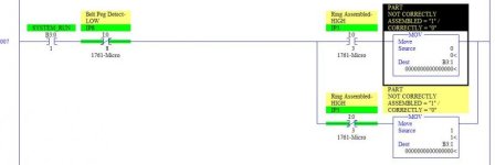
Hi Lancie, I do not understand your logic at rung #0007 using the MOV. From what I understand a part NOT correctly assembled will insert a "1" in B3:1 while a part that's correctly assemble will insert a "0" in B3:1 to avoid being kicked at the end of the conveyor.

The thing I don't understand is why do you have a XIC for IP8 for both output OR on that rung. What I mean is, how can a "1" be inserted in the FIFO source if the XIC for IP8 de-energized the whole rung and both MOV when a Belt or a Peg is detected unassembled?

Much appreciated,
Alex

ICT3_4.jpg
 
The thing I don't understand is why do you have a XIC for IP8 for both output OR on that rung. What I mean is, how can a "1" be inserted in the FIFO source if the XIC for IP8 de-energized the whole rung and both MOV when a Belt or a Peg is detected unassembled?
This is where the rubber meets the road. To know which instruction to use for IP8 (XIC as shown or XIO as you propose), you have to know HOW the IP8 sensor operates. Does the sensor "go LOW" when it see something, as indicated by the label right in your instructions, or does it "go HIGH" and OPENS a contact when it sees something? I AssUMed that it goes LOW or opens when it sees a part. In other words, it is a Normally Closed (N.C.) sensor as traditionaly defined. I think only YOU can tell because you have the Simulator program and I don't.

To make a NC sensor open, you have to trigger it with a part. Therefore, if you are looking at a NC physical sensor that is now OPEN, but you want your PLC instruction for that sensor to go closed (or HIGH) when the sensor opens (goes LOW), then you must use a XIO (think of the "O" as the "Opposite" of your physical switch).
 
XIO & XIC Truth Table
Physical
Input XIO XIC
1 0 1
0 1 O

Memory tricks:
For XIO: What you "see" on the input is Opposite of you get out inside the PLC.

For XIC: What you "C" on the input is what you get out inside the PLC.
 
Last edited:
Does the sensor "go LOW" when it see something, as indicated by the label right in your instructions, or does it "go HIGH" and OPENS a contact when it sees something?
I should correct this statement, where it says "does it 'go HIGH' and OPENS" should be "does it 'go HIGH and CLOSES a contact'.

Here is another way to handle the Reject Part tracking on the Belt Conveyor. You could use Indirect Addressing and a CTU and CTD Counters to keep up with the number of parts on the belt between IP4 and IP5. But some MicroLogix and SLC 5/01 and 5/02 PLCs do not provide Indirect Addressing, but you can use Indexed Addressing. Edited Rungs 0008 to 0012 show a way to use this INDEXED ADDRESSING method. It it really not any shorter than the FIFO method, but may appear easier to understand.
 
Last edited:
This is a very complicated program for me. I do not have the software simulator. I have to understand everything at a theoretical level and for this one, the lack of practical resource is slowing me down.

Where it says[...] it 'go HIGH and CLOSES a contact'.

From what I understand according to your explanation, likewise with the STOP button that's N/O and in fact does the opposite when you consider the logic behind the actual hardware switch, this Belt Peg Detect - LOW (which I AssUMEd means an analogue input sensor) meaning that what I see (in ladder programming) is the opposite of what it does. Meaning, when it will go HIGH it will close the contact like a normally opened relay. But since it has the attribute of being LOW, we have to AssUMe that it will do the opposite for the ladder input representation. Am I right with my ASSumptions? lol

Can you explain me the major differences between the FIFO logic you've used in Rev.1 and this Indexed Addressing for the Rev.2 ?

Much appreciated,
Cheers.
 
Last edited:
But since it has the attribute of being LOW, we have to AssUMe that it will do the opposite for the ladder input representation. Am I right with my ASSumptions? lol
In addition to the LOW and HIGH designations on you I/O list, I also observed the indicator lights on each sensor. When the ones marked LOW were not seeing anything (no object in front of the switch), the indicator was ON, which I think means that the sensor (digital not analog) output contact was CLOSED (allowing the built-in indicator light to turn ON). When these same sensors were tripped by a part, the light would go OFF, I think indicating that the sensor output was then LOW or OFF or OPEN or a binary "0". Go back and look at that video and let me know if you see the same thing. I am an old guy and sometimes get confused.

Can you explain me the major differences between the FIFO logic you've used in Rev.1 and this Indexed Addressing for the Rev.2 ?
I can only try to explain the differences. The basic difference is in the instructions used.

Method 1 uses the FFL (FIFO Load) and FFU (FIFO Unload) instructions. These instructions have built-in capabilities to keep up with the Number of objects, and also the Order of these objects. Then you can use the FFL to insert new objects as they occur, which advances the FIFO position indicator for each object. When you get rid of an object (rejected in this case), you trigger the FFU, which pushes the data for that object to the FFU Destination address. See the RSLogix Help file (click "Help, SLC Instruction Help, then select your instruction neumonic) to find the details for each instruction.

Method 2 uses Up and Down Counters and Indexed Addressing (because your MicroLogix does not have the capability for the easier Indirect Addressing). To use the Indexed Addressing method, you load an "offset" (a number to be added to a base address) to memory location S:24. Then when you use an Indexed adddress designation (put a "#" in front of an address, RSLogix automatically adds the value of S:24 to that address. In this way, you can in effect have a variable address that changes as needed for the process. So we can use the CTU and CTD to keep up with how many parts have passed IP4 but have not yet arrived at IP5. I figure that you could potentially have 3 or 4 parts, maybe even 5. If there are more than that, you should increase the Counter Presets to whatever the number of parts could possibly be between those points. Now that we have a way to count or index the number of parts, for each new part, we save the part condition (0 = good, 1 = reject, but you could use any numbers from 0 to 32767) to the B3:1 memory word by using Indexed Addressing and the Counter Accumulator value as the index value. This may be how the authors wanted you to do this task, since they did mention "index" in their description.

As Forest Gump said, "That is all I have to say about that right now".
 
Last edited:

Similar Topics

Hi everyone, I've got a strange problem. We have a machine that custom mixes chemicals and is controlled by a AB industrial PC talking to a AB...
Replies
7
Views
9,768
Hi Everyone, I am not proficient in RSLogix 500 so I have a question regarding the evaluation of N7:0 data as an input. So as I understand in...
Replies
1
Views
87
Hi folks, in the alarm manager of Rslogix 5000, the tag-based alarm has been created. But when I tried to change the condition, it was found the...
Replies
2
Views
157
I have a little bit of experience with Allen-Bradley. I have a Micrologix 1500 (RSLogix 500) and a PanelView Plus 7 (FactoryTalk View Studio ME)...
Replies
3
Views
170
Back
Top Bottom